www.gisma-connectors.de10Cabling Instructions series 10+22 Revision F - 11/2018
CABLING INSTRUCTIONS - SERIES 10 + 22
VORBEREITUNGEN ZUR VERKABELUNG -
SOLDERING CONTACTS
PREPARATION FOR THE CABLING PROCESS -
LÖTKONTAKTE
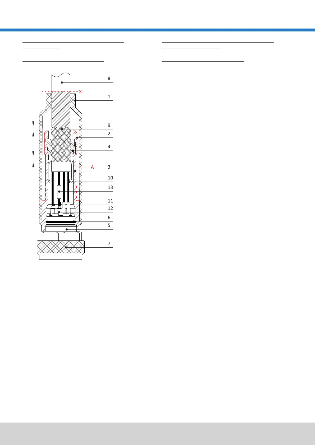
Complete structure of the connectorGesamtaufbau des Steckverbinders
2 Pressmutter
press nut
3 Endgehäuseadapter
1 Formteil
rubber boot
neoprene-leakage extension
13 Schrumpfschlauch (optional)
11 Lötkontakt
screen
soldering contact
cable
endbell adapter
Endgehäuse
6 O-Ring
wire
5 Steckergehäuse
Die Einzelteile des Endgehäuses (Pos. 2-3) müssen vor der Montage
entfettet und im Bereich A (s. Zeichng.) angeraut werden (Schmirgelleinen
oder Sandstrahlen). Das Anschlussgewinde des Steckers entfetten.
ACHTUNG: Die vorbereiteten Oberflächen (insbesondere Titan) sind
umgehend mit PRIMER 3 zu beschichten!
NOTE: Freshly prepared surfaces must be primed as soon as
possible, particularly titanium.
2.
4 konische Halbschalen
heat shrink tube (optional)
7 Überwurfmutter
endbell
locking sleeve
1.
The individual components (item 2-3) of the endbell must be degreased
and sandblasted in area A (as shown in the drawing) before assembling.
The connector thread must be degreased.
Nach dem Entfetten sind die Endgehäuseteile in der Reihenfolge von Pos.
1-3, wie in nebenstehender Skizze gezeigt, auf den Kabelmantel zu
schieben.
connector shell
8 Kabel
12 Neopren Kriechstromstrecke
conical clamps
O-ring
After degreasing push the endbell parts (item 1-3) onto the outer cable
jacket in the order shown in the drawing.
9 Schirm
10 Ader
max. 2 mm 2-5 mm
 Loading...