NOTE:
SW2
1 2 3 4 5 6
7 8
OFF
ON
1. Without the pump type water level switch output cables short circuit.
The power (HP) of indoor units can be set throughDIP switch SW1(16- bit disc DIP ) on
the indoor control panel before delivery, the detailed information is as follows:
Indoor models
Low static pressure duct unit
Indoor models Select bits
1 2
OFF
ON
OFF
ON
OFF
ON
OFF
ON
1 2
1 2
1 2
Floor&Ceiling Unit
Standard static pressure duct unit
High static pressure duct unit
OFF
ON
OFF
ON
SW2 NO.4
4
4
Display light board
LED
Digital tube
OFF
ON
OFF
ON
SW2 NO.5
5
5
power-down memory
No power-down memory
power-down memory
Room temp. sensor T1 for
Electric control panel
Wire controller
OFF
ON
OFF
ON
SW2 NO.8
8
8
OFF
ON
OFF
ON
SW2 NO.3
4
4
FAN SPEED CHOICE
High speed
Super High speed
Reserved
SW2 NO.6
ReservedSW2 NO.7
OFF
ON
OFF
ON
That DIP to OFF
That DIP to ON
1
1
NOTE:
FACTORY DEFAULT
MODEL
POWER
SW1
Reserved
Reserved
0
21
7K
1
26
9K
2
35
12K
3
53
18K
80
27K
6
90 105
36K
4
70
24K
5
30K
7 8
125
42K
9
140
48K
160
55K
C
180
A
150
52K
B
60K
D E
F
Reserved
Reserved
HP Reserved 0.8 1.0 1.5
2.0 3.0 3.5 4.02.5
4.5
5.0 6.0 6.55.5
Reserved
1.7
47
16K
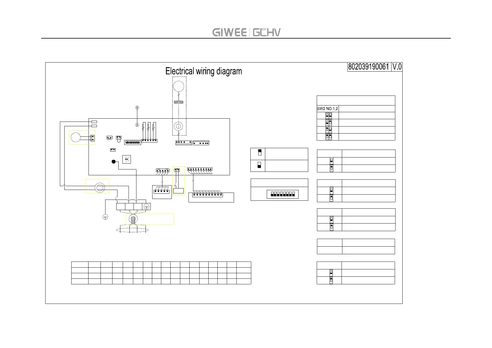
CN26
REMO_CTRL
CN27
CN23
T1
T2
T2B
CN17
0
F
1
SW1
CN10
CN3
L
N
Wire control
Duct display
SW2
Controller
Receive and display light board
BR
BL
1 2 3
4 5 6
7 8
OFF
ON
WATER
SWITCH
PUMP
CN18
Water-SW
5
10
CN2
PUMP
LEFT FAN CN7
RIGHT FAN CN8
PT1
PT2
PT3
S
CN37
CN4
HEATER
OUT POWER
CN11
N1L1 S
YE/GN
YE/GN
NOTE:Around the ring 5 ring
BL
BR
BK
Connect to the outdoor
Ring user selection
air temperature
sensor
middle temperature
sensor
outlet temperature
sensor
5
DC
FAN
NOTE:Around the ring 5 ring
5