Rev.: 4, Print date: 2021-05-05
14
NL95
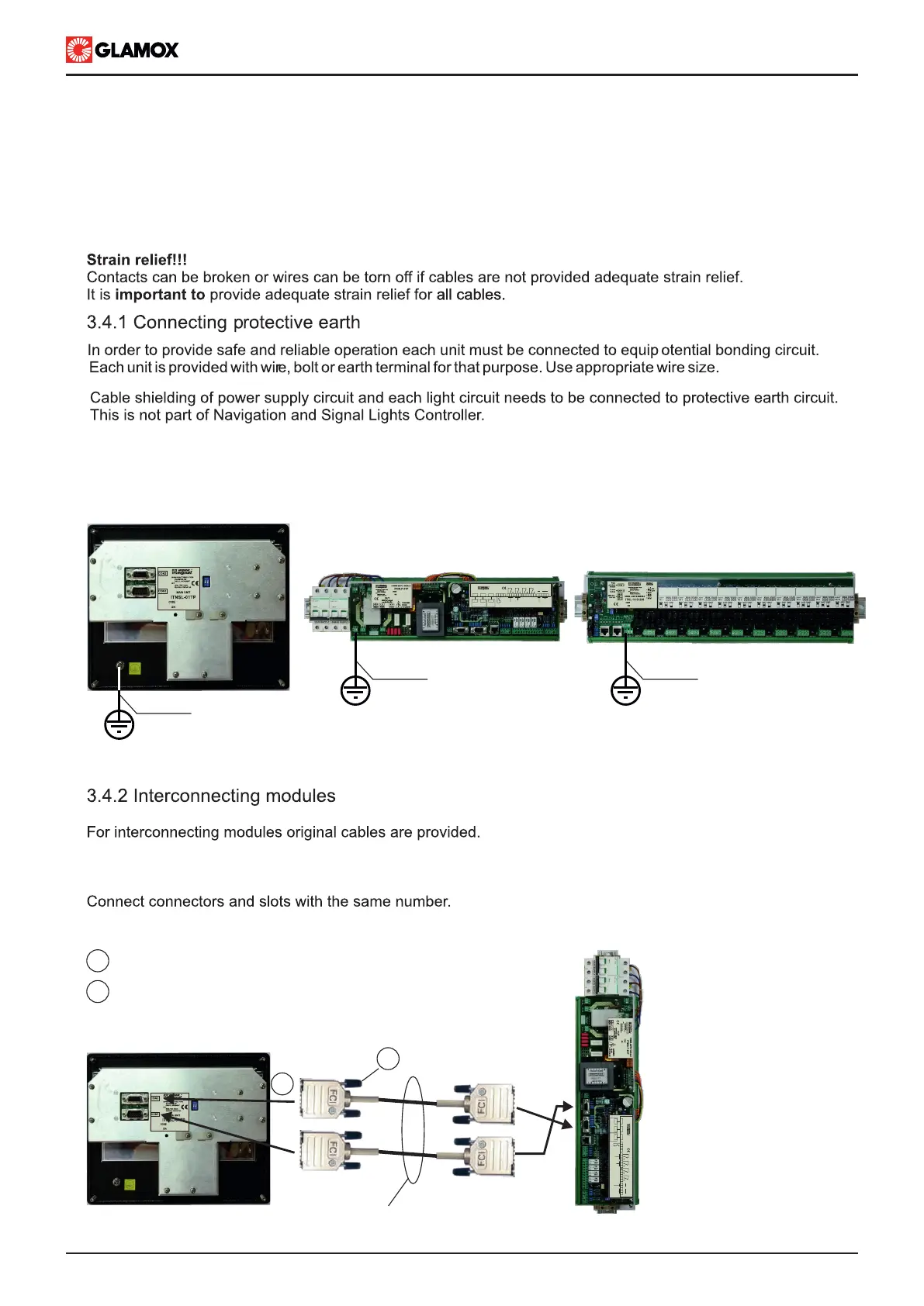
Main unit connected to Power Supply module via cables with DB9 connectors.
3.4 Connecting
Keep the following task sequence, when connecting Navigation and Signal Lights Controller :
1. Connect the protective earth
2. Interconnect all modules
3. Connect lights’ circuit
4. Connect power supply
5. Connect input / output contacts and communication
Shown 230/115 V ac modules
2
2.5 mm
CON1 CON2
MAIN UNIT
ITNSL-01TP
CON1 CON2
CON3
AUDIO ALARM ACCEPT INPUT
AL2
2 3 4 5 6 7 8 9 10 12 13 14 15 161
AL1 AL3SYS
C.O. VOLTAGE-FREE OUTPUT CONTACT
18 19 2017 21
SYSTEM OPERATING
COMMON ALARM OUTPUT
B A B A
-
RX TX
NMEA 0183
RECIEVER
NMEA 0183
TRANSMITTER
CON3
INPUT
MODULES
2
2.5 mm
2
2.5 mm
CON2
CON1
1
2
CON1
CON2
DB9 cables
1
2
Put connector in appropriate socket
Fix the connector screws
CON1 CON2
MAIN UNIT
ITNSL-01TP
CON1 CON2
CON3
AUDIO ALARM ACCEPT INPUT
AL2
2 3 4 5 6 7 8 9 10 12 13 14 15 161
AL1 AL3SYS
C.O. VOLTAGE-FREE OUTPUT CONTACT
18 19 2017 21
SYSTEM OPERATING
COMMON ALARM OUTPUT
B A B A
-
RX TX
NMEA 0183
RECIEVER
NMEA 0183
TRANSMITTER
CON3
INPUT
MODULES
Protective earth of navigation and signal light is not considered. If connection of protective earth is required, it
needs to be connected directly to protective earth circuit of ship and not through input modules.
 Loading...