Rev.: 4, Print date: 2021-05-05
33
NL95
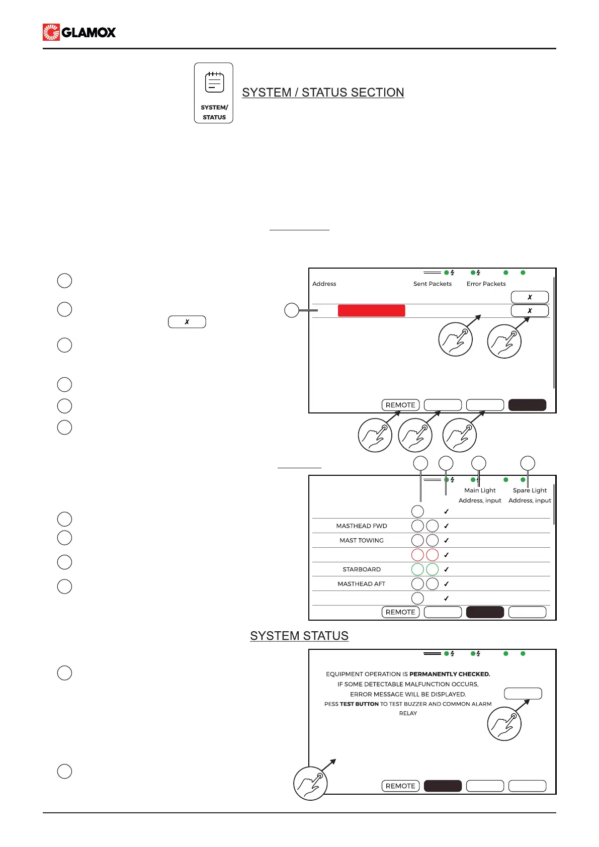
To reset communication alarm tap on
“Clear Error” button
1
2
List of configured modules, Communication
alarm on module with address no. 2.
Sent Packets, Error Packets - numerical
presentation of communication based on
which alarm is initiated.
Tap on Lights to show light list status
Tap on to show Remote control status.
Please check separate document for more information
5
6
3
4
Tap on to show system status
Light status provides information on each light,
their configuration and status as well as location
and position on module.
1
Tap on TEST to start system test.
- Internal buzzer of display will be activated
for 2.5 seconds
- Power Supply module buzzer and AL1 up
to AL3 will be activated for 2.5 seconds.
- System test finished, TEST button will
return to black.
2
Current status of inputs.
System/status screen provides detailed information of system and its current operation.
It is divided in 4 sections:
- Modules : Information on Input modules configured with their address as well as their communication status
- Light : Information on lights configured, their status as well as their location and position on Input modules
- System : Information on current input/output status. Status of input contact will be shown on display. Test
button for testing built-in buzzer and output relay.
- Remote : Please check separate document.
Modules screen provides info on modules that are configured and their current communication status. In case
that Input module communication error is detected, alarm will be triggered. To reset alarm tap on clear error
MODULES
1
2
3
4
Lights properties
Information if light alarm is enable or not.
Please. check configuration screen
Main light location (module address)
and position (input channel)
Spare light location (module address)
and position (input channel)
MAIN
EMERG.
SYS
MODULES
Module type
Clear Error
1
2
ITNL-10-D 62
62
0
10
LIGHTS
SYSTEM
MODULES
ITNL-10-S
No.
Light Name
Al.
1
2
3
4
5
6
7
SYSTEM
MODULES
LIGHTS
ANCHOR FWD
PORT
ANCHOR AFT
M
S
M
S
M
S
M
S
M
S
M
M
OFF
1.Lt.1
OFF
1.Lt.2
OFF
1.Lt.3
OFF
1.Lt.4
OFF
1.Lt.5
OFF
1.Lt.6
OFF
1.Lt.7
OFF
1.Lt.1
OFF
1.Lt.2
OFF
1.Lt.3
OFF
1.Lt.4
OFF
1.Lt.5
OFF
1.Lt.6
OFF
1.Lt.7
MODULES
LIGHTS
SYSTEM
TEST
IN1 :
IN2 :
IN3 :
VDR :
SYS :
AL1 :
AL2 :
AL3 :
OFF
OFF
OFF
-
ON
OFF
OFF
OFF
1
2
45
3
6
1
2
LIGHTS
21 3 4
MAIN
EMERG.
SYS
MODULES
MAIN
EMERG.
SYS
MODULES
 Loading...