Rev.: 4, Print date: 2021-05-05
3
NL95
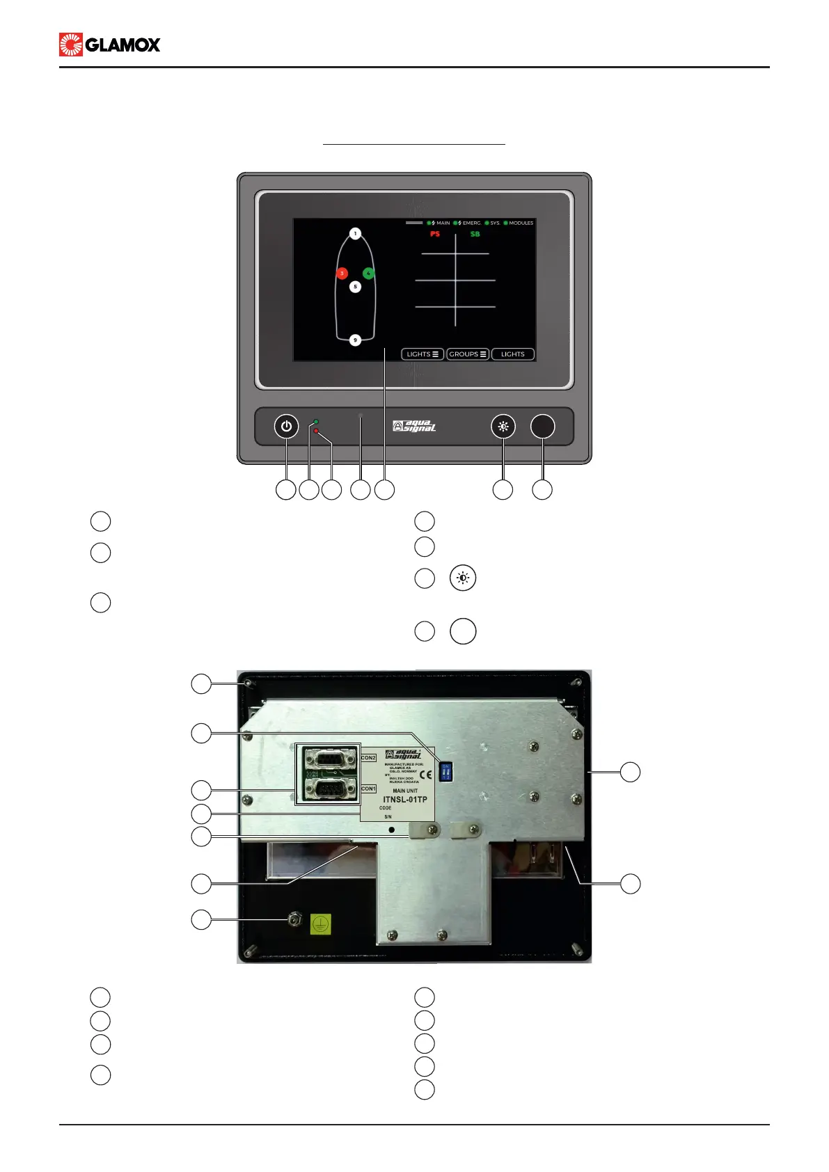
1.2 Design
2
1
“POWER ON/OFF”,
power on / power off system
FAILURE - LED indicates when ON :
(a) System total power supply failure
(b) Communication error between main unit
and Power Supply module
3
POWER ON - LED indicates when:
(a) ON - system is operating
(b) Blinking - System is powering up / booting
Buzzer
4
F2 key - for adjusting display intensity,
configurable via
CONFIG > PREFERENCES > F2 KEY
5
F1 key - general use key,
configurable via
CONFIG > PREFERENCES > F1 KEY
6
Touch screen display
7
MAIN UNIT ITNSL-01TP
F1
11
14
10
12
8
Back View
9
POWER ON
FAILURE
F1
Front View
1 2 3 4 51 6 7
13
8
9
10
11
12
Main unit label
Holders for fixing cables
Modbus RTU over TCP/IP RJ45 Cable input
Earth bolt
Mounting screws
DB9 connectors for inteface
with Power Supply module
13
14
End of line termination resistor dip switch
15
16
USB type A input port, for upload and download
15
SD card input slot, for upload and download
16