Rev.: 4, Print date: 2021-05-05
4
NL95
1 7
82
93
104
5
6
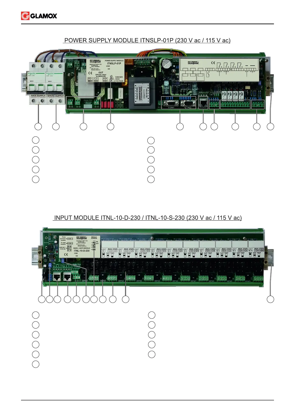
Input fuse, 0.2AF
Switches for manual light operation
RJ45 connector - from previous module
RJ45 connector - to next module
Input module power supply terminals TS35 rail for mounting
Fuses for lights, 1AF
11
Input terminals for lights connection
1
2
8
3
4
5
Input fuse for main power supply
Module label
Input fuse for emergency power supply
9
Terminals for NMEA 0183 communication
Power supply output for Input modules
10
TS35 rail for mounting
Output contacts for system operating / alarms
DB9 connectors for main unit connection
6
RJ45 connector for Input module connection
7
Input terminals for audio alarms silence
End of line termination resistor dip switch
Address selection dip switch
Module label, with addressing table
1 3
5
9 10 11
4
6
2
7
8
1 2 3
5 6 7 8 9
4
10
CON1 CON2
MAIN UNIT
ITNSL-01TP
CON1 CON2
CON3
AUDIO ALARM ACCEPT INPUT
AL2
2 3 4 5 6 7 8 9 10 12 13 14 15 161
AL1 AL3SYS
C.O. VOLTAGE-FREE OUTPUT CONTACT
18 19 2017 21
SYSTEM OPERATING
COMMON ALARM OUTPUT
B A B A
-
RX TX
NMEA 0183
RECIEVER
NMEA 0183
TRANSMITTER
CON3
INPUT
MODULES