6-6
BARHOLE TESTING MODE
USER HANDBOOK
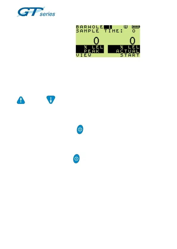
The rst barhole screen
is then displayed, as
shown in Fig. 6.9
Up to six barhole readings can be stored. These are identied as
‘Barhole 1’ to ‘Barhole 6’.
After the rst reading is stored (as Barhole 1), the second reading
(Barhole 2) will be automatically selected, however, by using the UP
or DOWN buttons the user can specify where the next
reading will be stored. This may be useful if there was a problem
with the reading, e.g. sample fault.
The sequence of events will be as follows:
• Press and hold START to initiate. This will switch the
pump ON. (START on bottom line of LCD will change to
STOP).
• Counter counts up from zero.
• Press and hold STOP when sampling is complete. The
pump will be switched OFF.
• View as per TIMED MODE.
• Purge mode as per TIMED MODE.
• From switch-on, each barhole is consecutively numbered
automatically.
Fig. 6.9 Non Timed Mode of
Operation

 Loading...