Do you have a question about the GMI PS241 and is the answer not in the manual?
Specific safety guidelines for CSA certified instruments.
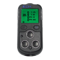
Provides a comprehensive overview of the PS200 series gas detector.
Lists the key features and capabilities of the PS200 instrument.
Details the data logging capabilities of the PS200 series instruments.
Explains how to download stored readings to a PC.
Describes the instrument's protective filters and replacement.
Information on the instrument's housing and durability.
Details the information found on the instrument's rear label.
Outlines the certifications and standards the PS200 complies with.
Step-by-step guide for operating the PS200 instrument.
How to power on the PS200 instrument.
Displays serial number, software version, and battery status during warm-up.
Shows the current charge level of the instrument's battery.
Allows users to assign a name or code for logs.
Displays the instrument's built-in clock date and time.
Notifies users about upcoming or overdue bump tests.
Indicates when the instrument's calibration is due or overdue.
Alerts users about upcoming or overdue service dates.
Allows selection of different calibration gases for accurate readings.
Verifies that sensors have been zeroed correctly.
Indicates a memory fault preventing instrument operation.
Shows the standard display after successful warm-up.
Manually toggles the display backlight for visibility.
Allows manual storage of data logs.
Displays the highest and lowest gas readings recorded since start-up.
Procedures for resetting or acknowledging active alarms.
Confirms instrument operation with periodic beeps and LED flashes.
How to perform remote gas sampling using the instrument's pump.
Details on starting, stopping, and operating the internal pump.
Performs a self-test of the instrument's functions.
Instructions on how to properly shut down the instrument.
Explains the purpose and process of bump testing sensors.
Describes the QUICK and FULL bump test options available.
Steps to start and confirm a manual bump test.
Choice of regulator valve for pumped instruments during bump tests.
How to apply test gas to the instrument for bump testing.
Details the outcomes of Quick and Full bump tests.
User confirmation of audible and visual alarms during bump test.
Displays whether the bump test passed or failed.
Details on how gas alarms are triggered and indicated.
Table showing default alarm types, latching, mute, audible, vibrating, and visual settings.
Describes the alarm levels for flammable gases (LEL).
Explains the safety alarm for exceeding 100% LEL.
Details the alarm levels for oxygen (O2) concentration.
Covers alarms for toxic gases, including STEL and LTEL.
How to acknowledge gas alarms once in a safe area.
Procedures for muting audible alarms temporarily.
Warning and indication for dangerous over-range flammable gas levels.
Information on various instrument faults and their indications.
Warning for low battery status and remaining operation time.
Indicates a fault in the sensor zeroing process.
Alerts to sensor integrity issues or electrical faults.
Warning for flow or sample line issues in pumped models.
Notifies when instrument calibration is overdue or required.
Indicates that the instrument's calibration date has passed.
Instructions for cleaning the instrument's exterior casing.
Procedures for inspecting and replacing the instrument's filters.
Detailed steps for replacing the sensor's hydrophobic filter.
Steps to replace the sample inlet dust filter.
Details on the in-line filter for moisture protection.
General guidance on recharging the battery.
How to charge the instrument using the comms clip.
Charging multiple instruments simultaneously with the 5-way charger.
Charging the instrument using a vehicle's 12V/24V socket.
Charging the instrument using a vehicle charging cradle.
Explains the importance and methods of instrument calibration.
Discusses user responsibility for maintaining calibration validity.
Details on available training courses for GMI products.
Provides the GMI company website address.
| Type | Pressure Switch |
|---|---|
| Protection Class | IP65 |
| Power Supply | 24 VDC |
| Contact Type | SPDT |
| Process Connection | G1/4" |
| Operating Temperature | -20...80°C |