EasyManuals Logo

GMI PS241 User Manual

GMI PS241
92 pages
To Next Page IconTo Next Page
To Previous Page IconTo Previous Page
Page #43 background imageLoading...
Page #43 background image
3-5
MANUAL BUMP TEST OPTIONS
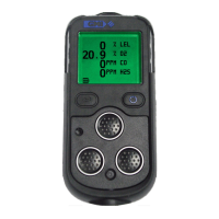
3.6 ALARM CONFIRMATION
The user is then prompted to conrm if the audible and visual
alarms were activated, as shown in Fig. 3-5.
Fig. 3-5 Conrm Alarms (4-gas model)
Note: The audible, visual and vibrating alarms activate for
2 seconds only (default setting) when activated during the
bump test.
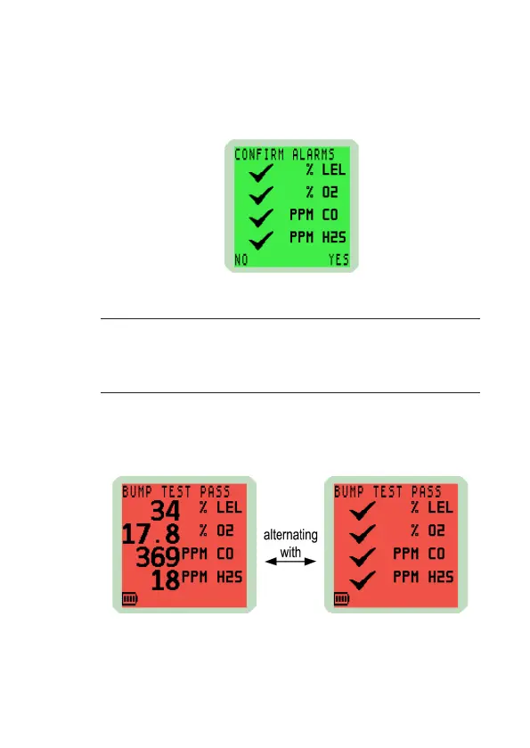
3.7 BUMP TEST RESULT
After selecting ‘YES’ the user is informed of the bump test
pass as shown in Fig. 3-6.
Fig. 3-6 Bump Test Pass
The bump test gas should now be removed.

Table of Contents

Questions and Answers:

Question and Answer IconNeed help?

Do you have a question about the GMI PS241 and is the answer not in the manual?

GMI PS241 Specifications

General IconGeneral
TypePressure Switch
Protection ClassIP65
Power Supply24 VDC
Contact TypeSPDT
Process ConnectionG1/4"
Operating Temperature-20...80°C

Related product manuals