4-9
ALARMS
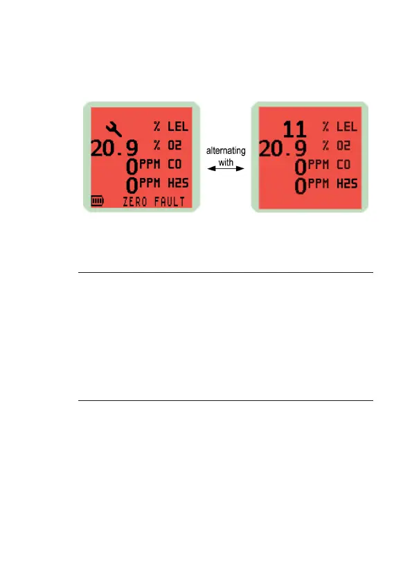
The faulty sensor will cause the instrument to display a
ashing spanner symbol to warn the user that this sensor is
not working correctly, as shown in Fig. 4-7:
Fig. 4-7 Zero Fault
4.5.3 Sensor Fault
Note: The PS200 instrument features continual toxic sensor
integrity detection. This may generate a sensor fault
indicated by a red illuminated backlight, audible
beeping and ashing red LED’s. Unlike zero fault,
it would only occur immediately after switch-on and
occasionally during operation. If this fault occurs, allow
instrument to run in fresh air for up to 20 minutes. If
fault does not clear, return instrument to an approved
Service / Repair facility.
There are three types of sensor fault as illustrated in the
following displays:
1. If a “SENSOR FAULT” warning and a spanner symbol
appears adjacent to a gas type, as illustrated in Fig. 4-8,
then the sensor requires replacement or an electrical
fault exists. Return instrument to an approved service
/ Repair facility.