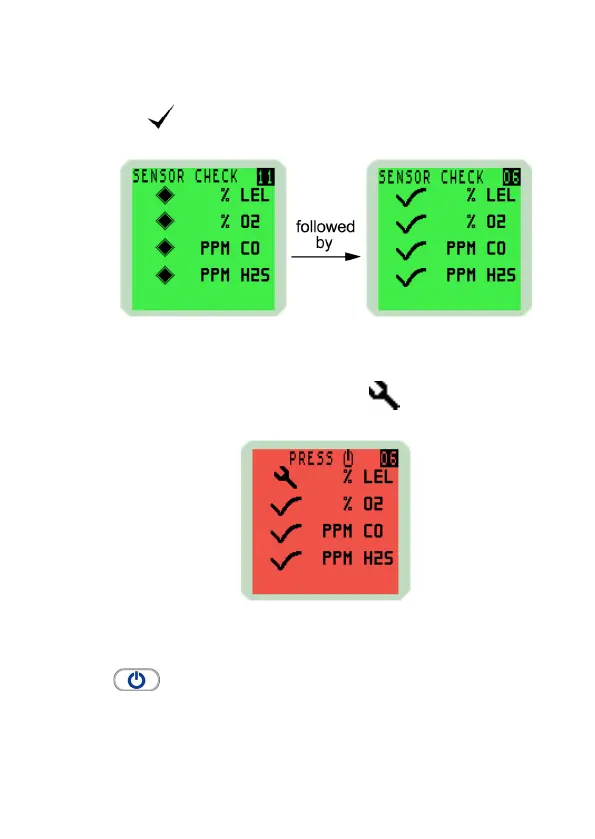
EasyManuals Logo

GMI PS241 User Manual

GMI PS241
92 pages
To Next Page IconTo Next Page
To Previous Page IconTo Previous Page
Page #29 background imageLoading...
Page #29 background image
2-9
OPERATION
2.2.9 Sensor Conrmation Check
The symbol appears adjacent to each sensor type to
conrm that the sensor has been zeroed correctly.
Fig. 2-11 Sensor Check Displays
If a sensor fails to zero correctly, the display will be red, the
audible / visual alarms activate and a symbol is displayed
adjacent to the faulty gas type, as illustrated in Fig. 2-12:
Fig. 2-12 Failed Sensor
To acknowledge this fault, press the Right Hand (RH) button
once. This will clear the audible / visual alarm and
display a ashing spanner symbol alternating with the faulty
sensor zero reading.

Table of Contents

Questions and Answers:

Question and Answer IconNeed help?

Do you have a question about the GMI PS241 and is the answer not in the manual?

GMI PS241 Specifications

General IconGeneral
TypePressure Switch
Protection ClassIP65
Power Supply24 VDC
Contact TypeSPDT
Process ConnectionG1/4"
Operating Temperature-20...80°C

Related product manuals