EasyManuals Logo

GMI PS241 User Manual

GMI PS241
92 pages
To Next Page IconTo Next Page
To Previous Page IconTo Previous Page
Page #23 background imageLoading...
Page #23 background image
2-3
OPERATION
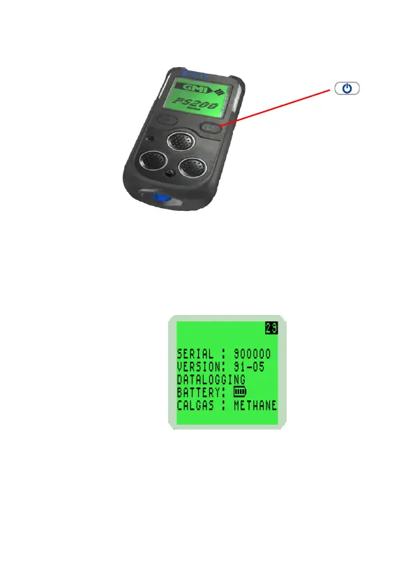
Fig. 2-1 PS200 Switch ON
2.2.1 Instrument Identication
During warm-up, the instrument display identies the serial
number, software version and battery status information as
illustrated in Fig. 2-2:
Fig. 2-2 PS200 Series Identication Display
2.2.2 Battery Status
Provides the user with the battery charge level, as shown in
previous display. This will be indicated by a battery symbol
with a bar graph showing FULL, 75%, 50% and 25%, which
is shown continually during normal operation.
RIGHT HAND (RH)
BUTTON

Table of Contents

Questions and Answers:

Question and Answer IconNeed help?

Do you have a question about the GMI PS241 and is the answer not in the manual?

GMI PS241 Specifications

General IconGeneral
TypePressure Switch
Protection ClassIP65
Power Supply24 VDC
Contact TypeSPDT
Process ConnectionG1/4"
Operating Temperature-20...80°C

Related product manuals