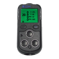
5-4
USER HANDBOOK
1. Using a No.1 Pozidrive
®
screwdriver, unscrew then
remove the 2 Pozi Pan screws then remove the inlet
nozzle complete with inlet lter located in the inner recess
of the nozzle.
2. Push the sample inlet lter disc out of inner recess by
inserting a matchstick, or similar, into the inlet nozzle
outer recess..
3. Fit a new Sample Inlet Filter (Part No. 66084).
4. Press the new sample inlet lter disc into the inlet nozzle
shallow recess, with rough disc surface towards inner
surface of recess (sample side).
5. Fit the inlet nozzle. The inlet nozzle is moulded to t in
one direction only. Make sure that orientation is correct to
locate easily into the instrument front cover inlet.
6. Fit then tighten the 2 Pozi Pan screws using a No.1
Pozidrive
®
screwdriver.
Note: Care must be taken not to overtighten the screws.
5.2.3 In-line Hydrophobic Filter (Accessory)
The in-line hydrophobic lter assembly consists of the lter and
a luer tting on one side of the lter and a push-t connection
on the other, and is available as an accessory (Part No.
66485). The lter assembly is used to protect the instrument
from the ingress of water when sampling in moist conditions.
The lter is located between two lengths of sample line
tubing (Part No. 64118) and attached to the instrument via a
Sample Line Connector (Part No. 66045) as illustrated in
Fig. 5.3.
 Loading...