5-3
OPERATOR MAINTENANCE
3. Fit a new Hydrophobic Filter (Part No. 64254).
4. Carefully place the hydrophobic lter in position over the
instrument sensors, locating lter pin holes over locating
pegs in instrument lter recess.
5. Place the lter cover over the lter recess then carefully
slide it towards the display screen until the lugs are
located in the mating slots in the instrument lter recess.
Press the cover down on to the lter then, using a No.1
Pozidrive
®
screwdriver, tighten the captive screw until
secure.
Note: Care must be taken not to overtighten the cover screw.
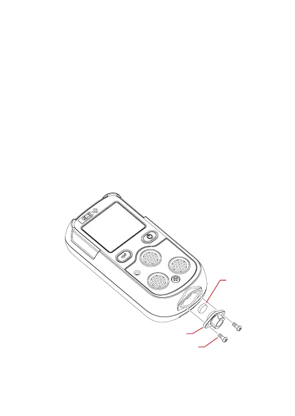
5.2.2 Replace Sample Inlet (Dust) Filter
SAMPLE
INLET FILTER
(Part No. 64084)
INLET NOZZLE ASSEMBLY
QUICK CONNECT
POZI PAN SCREW (2)
Fig. 5-2 Replace Inlet Filter