EasyManuals Logo

GMI PS241 User Manual

GMI PS241
92 pages
To Next Page IconTo Next Page
To Previous Page IconTo Previous Page
Page #30 background imageLoading...
Page #30 background image
2-10
USER HANDBOOK
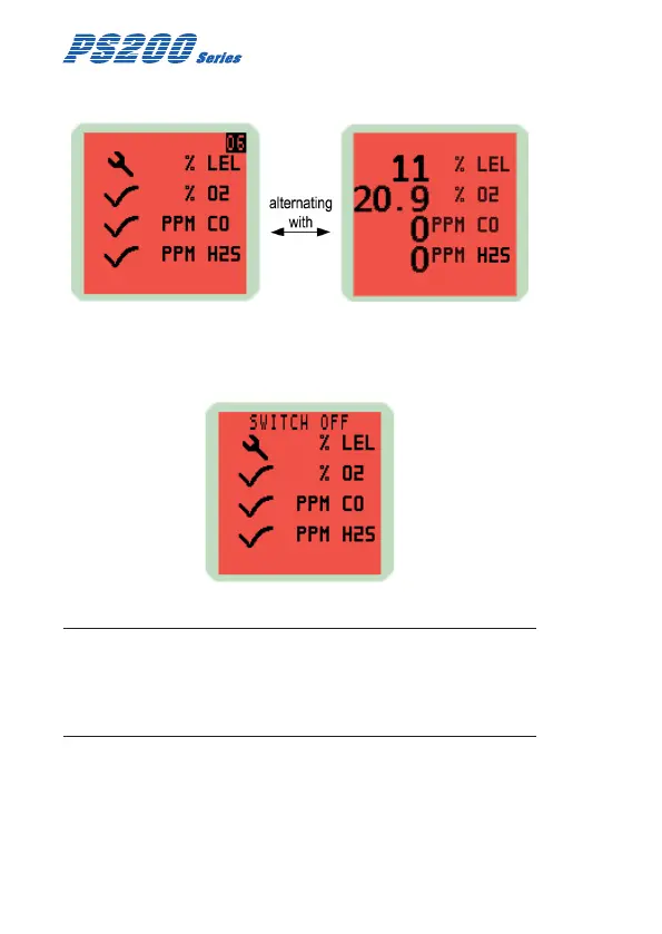
A faulty LEL sensor zero reading is shown in Fig. 2-13:
Fig. 2-13 Acknowledge Alarm
A congurable option is available to force the user to switch the
instrument off if a zero fault is detected, as shown in Fig. 2-14:
Fig. 2-14 Switch OFF
Note: If a sensor fault is detected during normal operation of
the instrument, the backlight illuminates red, an audible / visual
alarm is activated immediately and a spanner symbol is shown
adjacent to the faulty sensor type in the display.

Table of Contents

Questions and Answers:

Question and Answer IconNeed help?

Do you have a question about the GMI PS241 and is the answer not in the manual?

GMI PS241 Specifications

General IconGeneral
TypePressure Switch
Protection ClassIP65
Power Supply24 VDC
Contact TypeSPDT
Process ConnectionG1/4"
Operating Temperature-20...80°C

Related product manuals