Book No.: 95-0014-0000/A OPERATOR
Issue: 06 HANDBOOK
Page 13 of 30
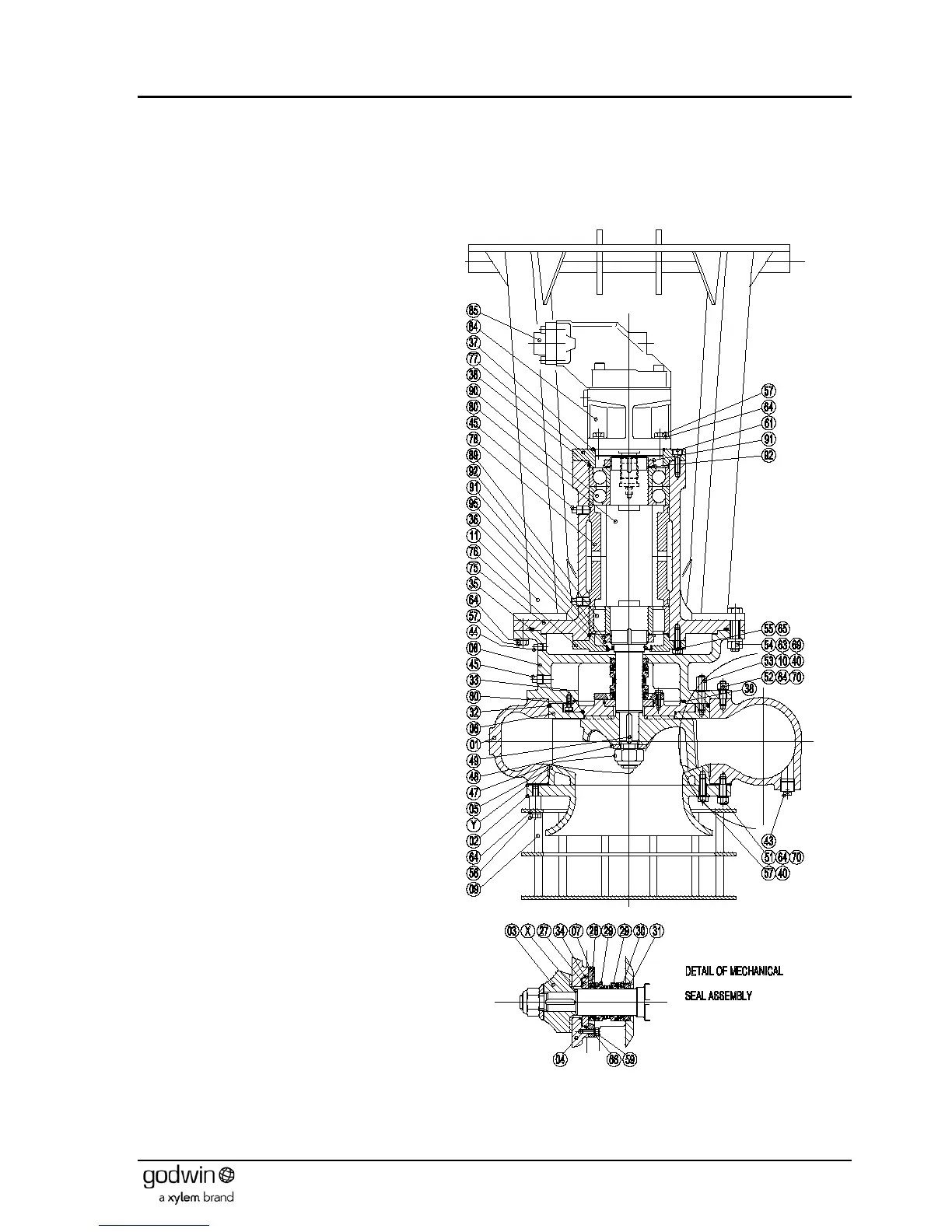
7.3 HS150HH, HS200-SG, HS200 & HS250 pumps
Note that dismantling and reassembly procedures refer to the item numbers in the illustration and are correct for a
directly corresponding build. However because of the number of possible build configurations some interpretation of the
diagram will be necessary for other pump variants. Some additional illustrations have been included to aid in this
purpose.
7.3.1 Dismantling
1. If not previously done remove the plugs (45)
from the bearing bracket (75) and drain the
oil. Remove the plug (44) from the adaptor (8)
and drain any leakage.
2. Remove the plug (45) from the adaptor and
drain the seal housing of oil.
3. Undo set screws (56) holding the strainer (9)
to the pump body (1). Remove strainer.
4. Release the nuts (70) holding the bearing
bracket, adaptor, wear plate and impeller
assembly to the pump body (1). (NOTE.
These are the nuts on the larger PCD. The
screws on the smaller PCD retain the wear
plate to the bearing bracket).
5. Extract the bearing bracket assembly from the
pump body (1). The front cover (2) and wear
plate (5) may be removed from the body by
releasing the nuts (70). The front wear plate
can be removed from the front cover by
removing the screws (57).
6. Place a bar through the vanes of the impeller
(3) to lock it in position and prevent rotation.
Unscrew (RH thread) and remove the impeller
retaining nut (47) and washer (48). Note that
the nut has a nylon insert that provides a self-
locking function. The nut will therefore remain
stiff to turn until this nylon insert is clear of the
shaft.
7. Pull the impeller (3) off the shaft (80) and
remove the key (49). Four off M8 tapped
jacking screw holes are provided in the boss
of the impeller if required to aid in its removal.
Shims (15, 16, 17 & 18) may be found on the
shaft behind the impeller. These have been
used to achieve the required rear clearance.
Keep a check on quantity and thickness for
comparison purposes when rebuilding.
8. Release the nuts (10) holding the rear wear
plate (6) to the bearing bracket assembly.
Remove the wear plate.
9. Undo and remove the socket head cap
screws (60) holding the inner wear plate and
seal carrier (4) to the adaptor (8). Remove
this inner wear plate with care as it carries the
seal seat (27). Once removed, the seal seat
can be removed from the wear plate by
undoing the screws (59) to release the seal
clamping plate (7).
10. The mechanical seals (29) are now exposed
and can be released by undoing their
clamping screws. Ensure that the screws are
fully retracted before moving the seals to
ensure that they do not mark the shaft during
removal. Slide the mechanical seals (2 off 29)
off the shaft (80) and extract the seal seat from
the adaptor (8).
Figure 10 Typical HS200 pump