Book No.: 95-0014-0000/A OPERATOR
Issue: 06 HANDBOOK
Page 21 of 30
7.5.2 Reassembly
7.5.2.1 GUIDE PIN FITTING
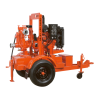
The HS100NC and HS150NC are fitted with a ’chopper’ insert ring. It is critical to efficient operation of the
pump that the guide pin used is fitted correctly.
Place impeller on flat surface – blades up.
Locate insert ring on the impeller, ensure the insert ring is
centralized on the impeller (Figure 20).
Figure 20 Locating insert ring on impeller
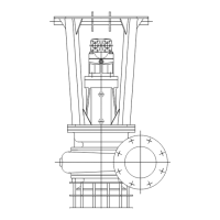
The guide pin comprises of three items, lip (1), cap screw (2) and nut (3)
(Figure 21).
Figure 21 Lip, cap screw and nut
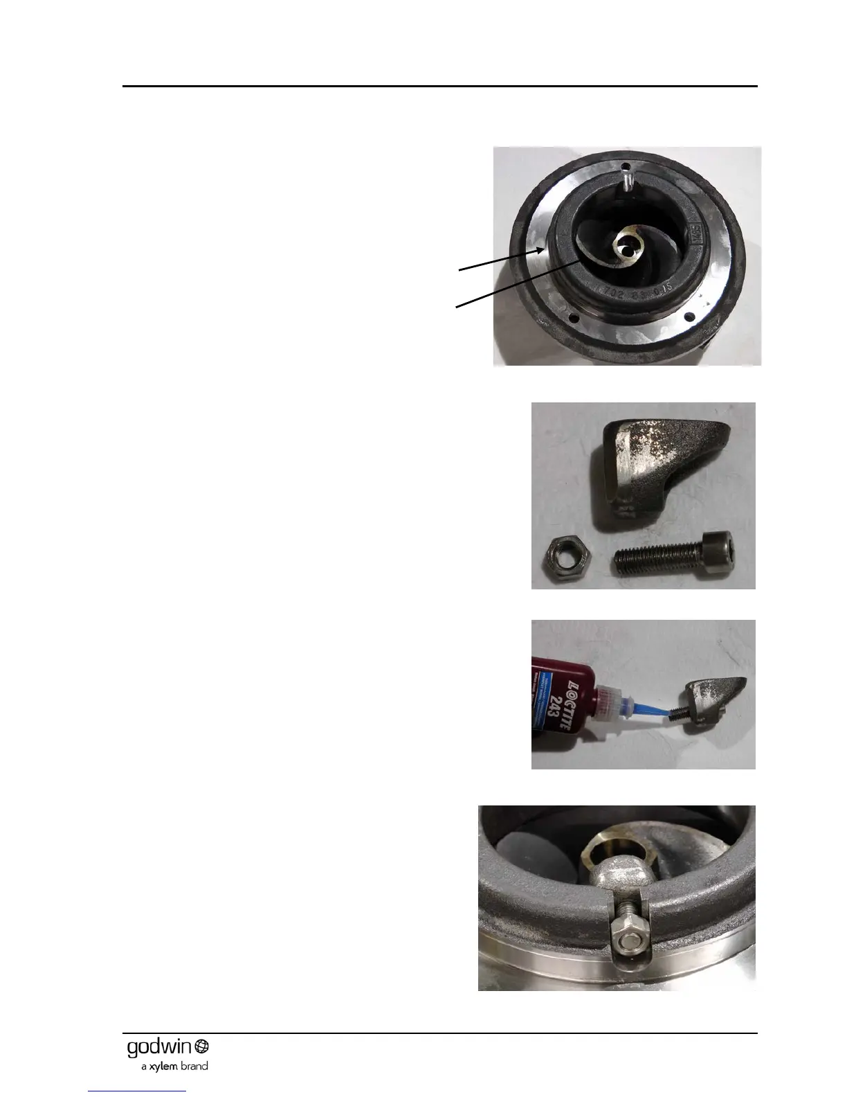
Assemble the cap screw into the lip and apply non setting thread lock
compound to the cap screw (Figure 22).
Figure 22 Applying non-setting thread lock compound
Place nut on to the cap screw and fit the assembly in to the
locating slot (Figure 23).
Figure 23 Locating guide pin assembly into insert ring
 Loading...