OPERATOR Book No.: 95-0014-0000/A
HANDBOOK Issue: 06
Page 24 of 30
7.5.2.3 ADJUSTING IMPELLER FRONT CLEARANCE
Unscrew and remove the impeller cap screw and flat washer.
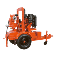
Using the Hexagon head (Allen bit) 12mm x 65mm long with extension bars (Figure 30 if needed) turn the adjustment
screw clockwise by hand until the impeller firmly makes contact with the wear plate (insert ring).
Figure 30 Hexagon head (Allen bit) and extension bar
Remove the Hexagon head (Allen bit), reach into the pump inlet and check the impeller cannot be rotated from this
position by hand.
Insert the anti-rotation bar through the access plug in the pump body to
prevent the impeller rotating.
Fit the lubricated impeller cap screw and flat washer.
Tighten the impeller cap screw to the correct torque using a torque
wrench, and then turn it an extra 1/8 turn (45°) with a wrench or bar.
(Check cap screw size and see Section 10.4
Table 2 for values).
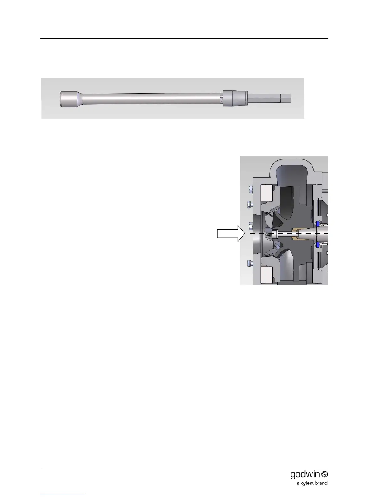
Using feeler gauges reach into the pump inlet and measure the
available impeller to wear plate (insert ring) clearance.
The minimum acceptable running clearance is 0.2mm (0.008”)
Important: Remove the anti-rotation bar and replace access plug in the
pump body.
Figure 31 Cross-section of pump inlet