OPERATOR Book No.: 95-0014-0000/A
HANDBOOK Issue: 06
Page 6 of 30
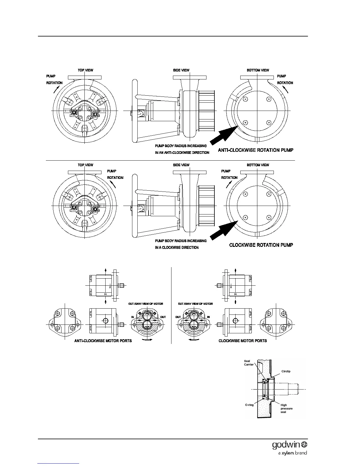
3. The output shaft from the motor is offset one way from the port centres in the body (see Figure 3). Ensure the
motor is in the correct orientation to Figure 3 and identify the motor ports accordingly. Mark appropriately. Note
that the hydraulic fluid passes around the outside of the gear wheels and not through the middle.
4. Connect the high pressure feed to the ‘IN’ inlet port and the low pressure return to the outlet port.
Figure 2 Pump rotation
Figure 3 Hydraulic motor ports
5.2.2 Front seal removal
The bearings (and mechanical seal for HS80 units) of HS80, HS100, HS150, HS100-SG,
HS150V, HS150V-SG, HS100NC and HS150NC pumps are designed to be lubricated
and cooled by the hydraulic motor system oil. The oil is bled from the motor by removing
the seal from the front cover. A typical motor front cover arrangement is shown in Figure
4. Removing the circlip allows the seal and O-ring to be withdrawn. On some pumps the
seal is fitted from the inside of the front cover. In these cases the front cover will need to
be removed prior to removing the seal.
Note that this oil is returned to the hydraulic reservoir by a separate leakage line (see
Figure 1).
On all other pumps the bearings and mechanical seal are enclosed in their own
separately sealed housings and the motor seal must not be removed.
Figure 4 Typical motor front seal