Book No.: 95-0014-0000/A OPERATOR
Issue: 06 HANDBOOK
Page 19 of 30
26. Fit 4 off studs (67) every other hole in the pump body. Fit 4 off studs (68) in the remaining holes. Pass the front cover
assembly over the studs and secure with 4 off nut and spring washers (74 & 81) on the shorter studs.
27. Measure the clearance between all impeller vanes and the front wear plate. Take the average and compare with the
running clearance given in the Technical Data section. If required add or remove shims (33, 34, 35, 36) as
appropriate.
28. Pass the strainer support (9) over the front cover and studs, locating it so that the larger holes in the support fit over
the previously fitted nuts. Secure in place with 4 off nuts and spring washers (74 & 81).
29. Attach the strainer (10) to the strainer support with 8 off nuts, bolts, and washers (81, 74 & 62).
30. Rotate the whole assembly so that the shaft is vertical (strainer down) Tilt the lifting bracket (100) to angle of about
20° with the open side up and lift the pump assembly into place, allowing the frame to return to the vertical as it is
done. Position within the bracket so that all securing bolts can be fitted. Secure with the appropriate nuts, bolts and
washers.
NOTE: - Tolerances between the pump assembly and the lifting bracket can be several millimetres. It is recommended
that the pump foot is fitted directly to the bracket and space elsewhere is made up with washers.
Assembly is now complete, but before attaching the hydraulic lines, the unit must be filled with oil in both the bearing
bracket and seal chambers.
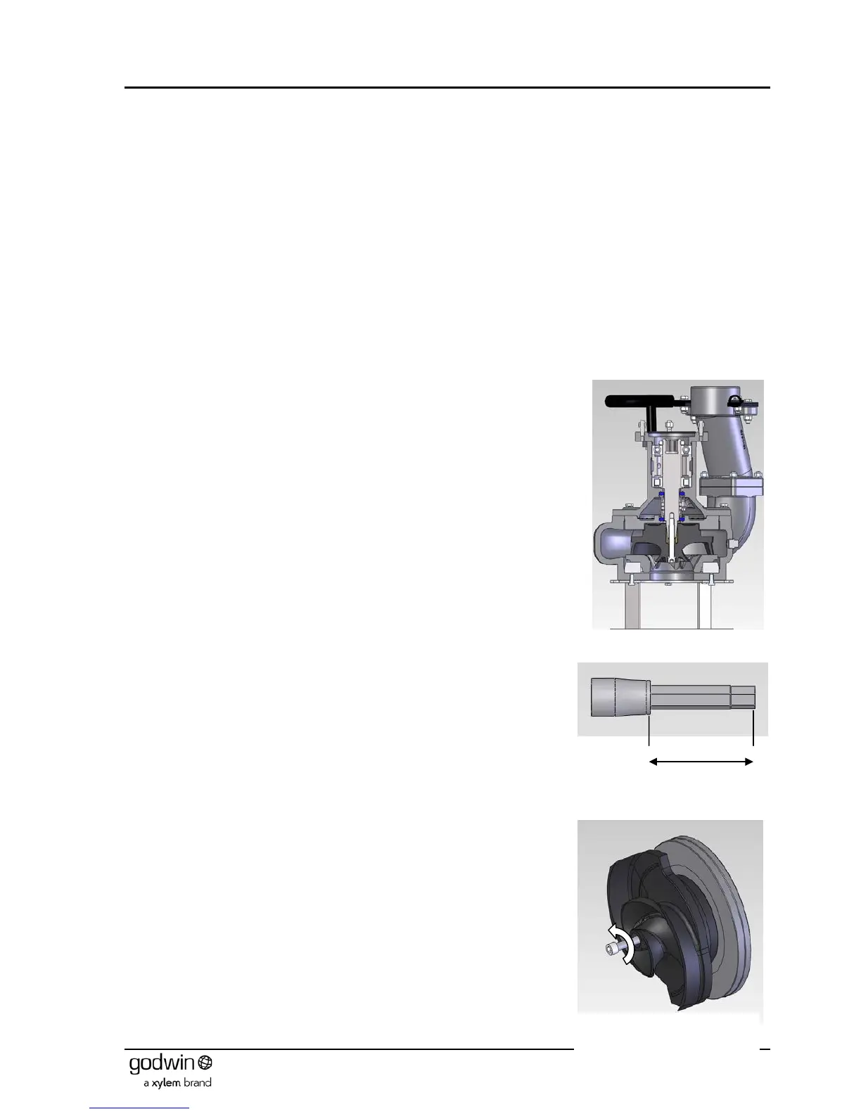
7.5 HS100NC & HS150NC Pumps
The HS100NC and HS150NC pumps share many parts with the 10022 and15022
pumps, differing only in the volute, impeller and associated items. Therefore the
method of dismantling and reassembly follow almost exactly the same procedures
(see section 7.2) except for the following:-
7.5.1 Dismantling
After removing the strainer, the impeller must be loosened slightly before extracting
the bearing bracket assembly (including the impeller) from the pump body.
Loosening the impeller will require the following tool in addition to a standard Allen
key required to remove the impeller locking screw:
½” drive Hexagon head (Allen bit) 12mm x 65mm long (Figure 15
).
Remove access plug from pump body (shown in Figure 14) and insert an anti-
rotation bar to prevent the impeller rotating.
Remove the impeller retaining cap screw (Figure 16) and washer (see Figure 17).
The impeller will still be retained by the friction fit of the sleeve between the shaft
and the impeller. Even if it this is dislodged the impeller will be retained within the
body.
Figure 14 Typical HS100NC pump