OPERATOR Book No.: 95-0014-0000/A
HANDBOOK Issue: 06
Page 20 of 30
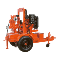
Figure 17 Typical HS100NC & HS150NC cross sectional view
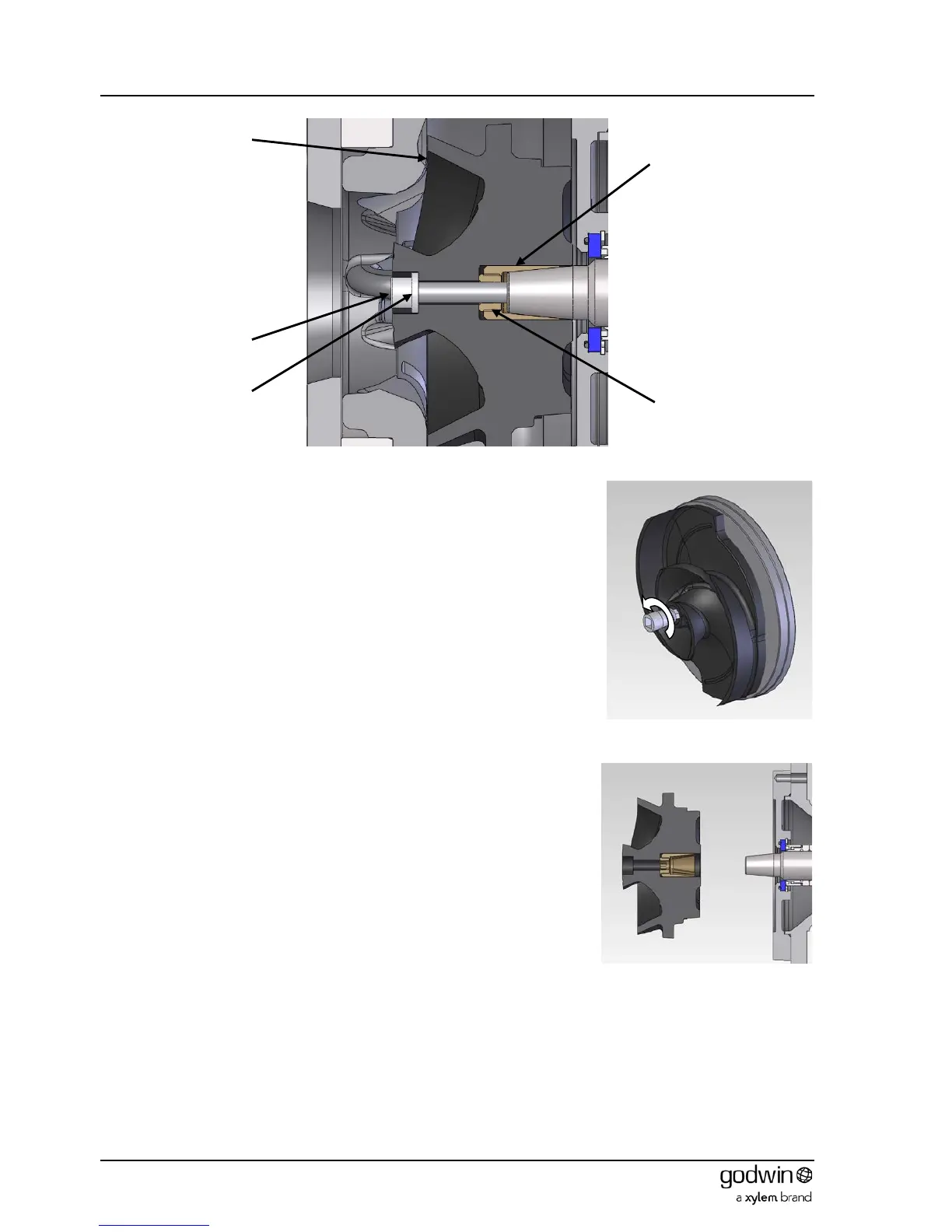
To break the friction fit between the impeller sleeve and the shaft, the adjustment
screw is turned anticlockwise (it is left hand threaded -Figure 18 ) using the 65mm
long Allen key (Figure 15). Turn sufficiently until it contacts the shaft and just breaks
the engagement.
Refit the impeller washer and screw hand tight as a security measure. This will
ensure that the impeller is retained on the shaft when the bearing bracket assembly
is removed from the volute.
The impeller is then removed from the shaft be undoing and removing the hand
tight impeller screw and washer. The impeller , impeller sleeve and adjustment
screw can then be removed.
All remaining dismantling procedure follow those in section 7.2.1.