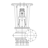
Book No.: 95-0014-0000/A OPERATOR
Issue: 06 HANDBOOK
Page 17 of 30
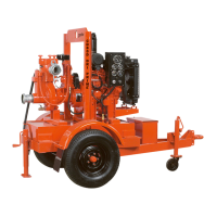
3. Using suitable lifting gear rotate the whole unit 90° until it is resting with the shaft horizontally and the pump mounting
foot towards the ground.
4. Remove the 4 off nuts, bolts and washers (81, 74 & 62) holding the strainer to the frame.
5. Support the strainer (10) and remove the 8 off nuts, bolts and washers (81, 74 & 62) holding it to the strainer support
(9). Slide the strainer out sideways from the frame.
6. Steady the strainer support (9) and remove the 4 off nuts, & washers (81 & 74) holding it to the front cover (2). Ease
the strainer support forwards until access can be gained to the nuts holding the front cover to the pump body (1). Let
it rest on the front cover.
7. Remove the 4 off nuts and washers (81 & 74) holding the front cover to the pump body. After removal attach suitable
lifting gear to the front cover and loose strainer support. Fit 4 off M12 x 45 (minimum length) screws to the holes in
the front cover and jack it (complete with front wear plate and loose strainer support) clear of the pump body (1).
Remove this assembly sideways from the frame.
8. Remove the loose strainer support from around the front cover. The front wear plate (5) and the front of the impeller
(3) may now be inspected for wear or damage. If necessary, the front wear plate can be detached from the front
cover by removing the retaining nuts and washers (72 & 80).
9. Inspect the hydraulic motor end of the shaft. If there are two flats on the top diameter, then an anti-rotation tool is
available to aid in further dismantling. If there are no flats then a suitable block of wood must be wedged between an
impeller blade and the pump body discharge to prevent rotation. Fit the anti-rotation tool or wedge the impeller.
10. Remove the cover (item 19 - 80mm A/F) in the centre of the impeller (3) to expose the retaining screw (64).
11. Knock down the tab on the tab washer (18) and slacken the retaining screw (64) to remove the tension. Do not undo
by more than one or two turns. The impeller will be removed later in the procedure. If the impeller was wedged in
position, remove the wedge.
NOTE: - If only the mechanical seal requires replacement carry out instructions 15 to 22 at this point and then
reassemble.
12. Return the frame and remainder of the pump to the upright position. Support the bolted in cross member whilst
removing its fastening bolts, nuts and washers (105, 107, 108 & 109). Remove the cross member.
13. Remove the 8 off nuts and washers (81 & 74) attaching the bearing bracket and adaptor assembly to the pump body
(1).
14. Attach suitable lifting gear to the bearing bracket and adaptor assembly and using the screws (59), jack the assembly
(including the impeller) clear of the pump body. Remove this assembly to a suitable place for further dismantling.
15. With the removed assembly horizontal, completely undo the impeller retaining screw (64) and remove the tab washer
(18) and impeller washer (16).
16. Pull the impeller (3) off the splines on the shaft (23). Note the number and size of shims on the shaft behind the
impeller for reference when re-assembling. NOTE:- The face against which the impeller is fitted is part of the
mechanical seal assembly and care must be taken not to damage it any way during further dismantling. The exposed
rear wear plate (6) can now be inspected for wear or damage.
17. If fitted remove the anti-rotation tool.
18. To remove the rear wear plate (6), remove the 6 off nuts and washers (80 & 72) securing it to the adaptor. Using the
2 off screws (61) the rear wear plate can be jacked off the adaptor.
19. 4 off socket cap screws (56) are now exposed. Undo them to remove the inboard seal seat carrier (item 4 wear
plate). Take care in removal not to damage either the seal seat attached to the back of the carrier or the seal sleeve
on the shaft.
20. Remove the 4 off screws and spring washers (57 & 71) holding the seal clamp ring (7). Push out the inboard seal
seat (12).
21. The double mechanical seal (13) is a one piece assembly and it can now be withdrawn from the shaft.
22. The outboard seal seat carrier (11) can now be released from the adaptor (8) by undoing and removing the 4 off
socket cap screws and washers (55 & 70). The outboard seal seat (14) can now be pushed out of the carrier (11).
23. Separate the adaptor (8) from the bearing bracket (20) assembly by undoing and removing the 8 off nuts, bolts and
washers (63, 74 & 81).
24. Undo the screws and spring washers (60 & 73) and remove the bearing cover (22) from the bearing bracket (20).
25. Press the shaft assembly out of the bearing bracket from the pump end.
26. The pump end bearing cover (21) can be removed from the bearing bracket (20) by releasing the 6 off screws and
spring washers (58 & 72).
27. Remove the spacer (28) from the bearing bracket.
28. Press the roller bearing outer race (part of 24) out of the bearing bracket.
29. Flatten the locking washers (26) tags, prevent the shaft from rotating, and unscrew the bearing locknuts (27).
30. Pull the 2 off angular contact ball bearings (25) off the shaft.
31. Pull the roller bearing inner race (part of 24) off the shaft.
32. The pump body (1) may now be removed from the lifting frame (100).
Dismantling is now complete. Inspect all parts for damage or wear.