9
User Manual V1.1-2022-07-20
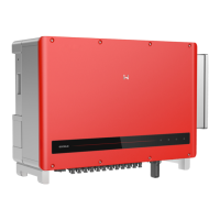
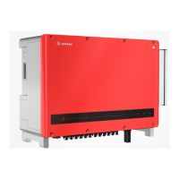
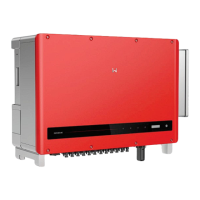
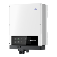
03 Product Introduction
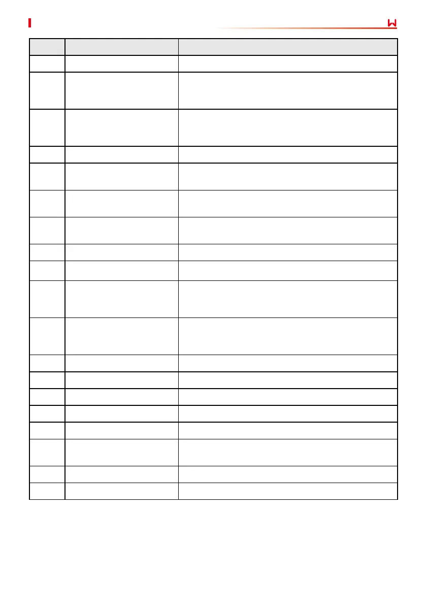
No. Parts Description
1 DC Switch 1-3 Start or stop 1-3 DC input.
2
PV Input Terminal 1-3
(Controlled by DC Switch
1-3)
Used to connect the PV module DC input cables.
3
PV Input Terminal 7-9
(Controlled by DC Switch
7-9)
Used to connect the PV module DC input cables.
4 DC Switch 7-9 Start or stop 7-9 DC input.
5 Communication Port
Used to connect communication modules like
Bluetooth, WiFi, GPRS, 4G, etc.
6
Communication Port
(RS485)
Used to connect the RS485 communication cable.
7
Communication Port
(Remote Shutdown)
Used to connect the Remote Shutdown communication
cable.
8 AC Cable Outlet Hole -
9 DC Switch 4-6 Start or stop 4-6 DC input.
10
PV Input Terminal 4-6
(Controlled by DC Switch
4-6)
Used to connect the PV module DC input cables.
11
[a]
PV Input Terminal
10-12(Controlled by DC
Switch 10-12)
Used to connect the PV module DC input cables.
12 DC Switch 10-12 Start or stop 10-12 DC input.
13 Ventilation valve -
14 Reserved Port Reserved.
15 Indicator Indicates working state of the inverter.
16 LCD (optional) Optional. Used to check the parameters of the inverter.
17 Button(optional)
Optional. Used to control contents displayed on the
screen.
18 Fan Used to cool the inverter.
19 Grounding Point Used to connect the PE cable.
[a]. The number of PV terminals varies depending on the dierent inverters. The actual
accessories may dier.
 Loading...