EasyManuals Logo

Goodwe HT Series User Manual

Goodwe HT Series
59 pages
To Next Page IconTo Next Page
To Previous Page IconTo Previous Page
Page #26 background imageLoading...
Page #26 background image
22
06 Electrical Connection
User Manual V1.1-2022-07-20
WARNING
The PE cable connected to the enclosure of the inverter cannot replace the PE cable
connected to the AC output port. Both of the two PE cables must be securely connected.
Make sure that all the grounding points on the enclosures are equipotential connected
when there are multiple inverters.
To improve the corrosion resistance of the terminal, it is recommended to apply silica gel
or paint on the ground terminal after installing the PE cable.
The PE cable should be prepared by customers.
M8 ground OT terminals should be prepared by customers.
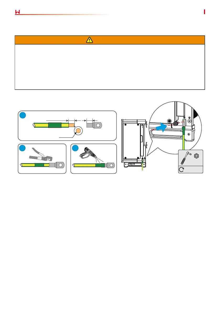
6.2 Connecting the PE Cable
L=L1+(1~2)mm
L1
1
2
3
M8
7~9N·m
S
PE
M8

Questions and Answers:

Question and Answer IconNeed help?

Do you have a question about the Goodwe HT Series and is the answer not in the manual?

Goodwe HT Series Specifications

General IconGeneral
Max DC Input Voltage1100V
MPPT Voltage Range200-1000V
Max AC Output Power3.6kW to 10kW
Number of MPPTs1 or 2
Max PV Input Voltage1100V
MPPT Range200-1000V
AC Output Frequency50/60Hz
CommunicationRS485, Ethernet
Operating Temperature Range-25°C to 60°C
Protection LevelIP65

Related product manuals