26
06 Electrical Connection
User Manual V1.1-2022-07-20
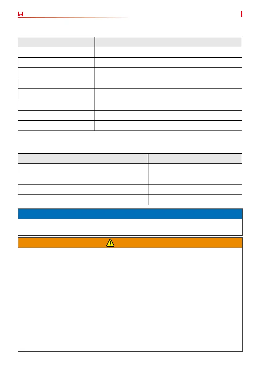
Inverter model AC circuit breaker
GW75K-HT/GW80K-HT/GW100K-HT 200A
GW110K-HT 250A
GW73KLV-HT/GW120K-HT 250A
GW125K-HTH/GW136K-HTH 225A
An AC circuit breaker should be installed on the AC side to make sure that the inverter can safety
disconnect the grid when an exception happens. Select the appropriate AC circuit breaker in
compliance with local laws and regulations. Recommended AC circuit breakers:
NOTICE
Install one AC circuit breaker for each inverter. Multiple inverters cannot share one AC circuit
breaker.
WARNING
• Pay attention to the silkscreens L1, L2, L3, N, PE on the AC terminal. Connect the AC cables
to the corresponding terminals. The inverter may be damaged if the cables are connected
inappropriately.
• Make sure that the whole cable cores are inserted into the AC terminal holes. No part of
the cable core can be exposed.
• Make sure that the cables are connected securely. Otherwise, the terminal may be too hot
to damage the inverter when the inverter is working.
• The AC terminals can be connected in three-phase four-wire or three-phase ve-wire. The
actual wiring method may be dierent. The gure below takes the three-phase ve-wire as
an example.
• The waterproof rubber ring for the AC outlet hole is delivered with the inverter, which is
located in the AC junction box of the inverter. Please select the rubber ring types according
to the actual using cables’ specication.
• Reserve certain length of PE cable. Make ensure that the PE cable is the last one to bear the
stress when the AC output cable is under tension.
• M8 ground OT terminals and M12 AC OT terminals should be prepared by customers.
Where an external RCD (Residual Current Device) is required in addition to the built-in RCMU
(Residual Current Monitoring Unit), and a type A RCD must be used to avoid tripping.
Inverter model Recommended RCD specications
GW73KLV-HT 730mA or higher
GW75K-HT 750mA or higher
GW80K-HT 800mA or higher
GW100K-HT 1000mA or higher
GW110K-HT 1100mA or higher
GW120K-HT 1200mA or higher
GW125K-HTH 1250mA or higher
GW136K-HTH 1360mA or higher
 Loading...