Version: V1.1 20
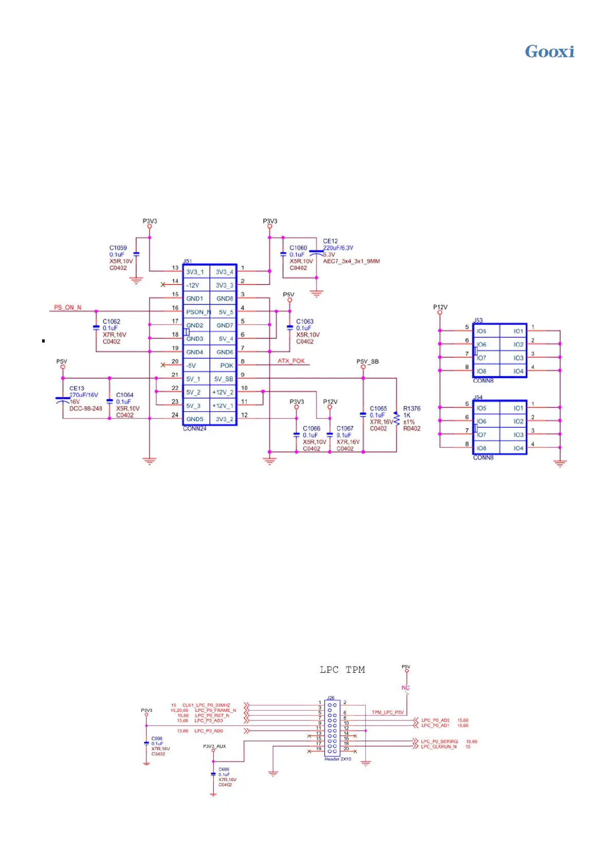
3/4/6) Power supply connector (J51/J53/J54)
J51 is a 2x12pin ATX power connector with a spacing of 4.2mm. When the wire diameter is 18AWG, a
single pin supports 6A. J53 and J54 are 2x4 ATX power connectors with a spacing of 4.2mm. When the
wire diameter is 18AWG, a single pin supports 7A. When the motherboard is working at full load, both
need to be connected.
Note: the connector connection method meets the ATX power supply specification, and the ATX power
supply can be directly used for power supply in the commissioning stage.
Figure 2-13
5) PMBUS interface
The motherboard supports power PMBUS management protocol
6) M.2 slot
The motherboard supports the installation of M.2 SSD of 1* 2280 specification. It only supports PCIe
protocol and does not support SSD of SATA protocol.
7) 2 MiniSAS SFF-8643 interfaces
Motherboard supports connecting 8* SATA HDD through 2* MiniSAS SFF-8643 interfaces.
8) LPC TPM expansion interface
The motherboard provides an LPC TPM expansion interface with 2x10pin NC Pin4 2.54mm pin. The
detailed signal definitions are as follows:
Figure 2-14
 Loading...