Version: V1.1 21
9) Front USB3.0 connector/header
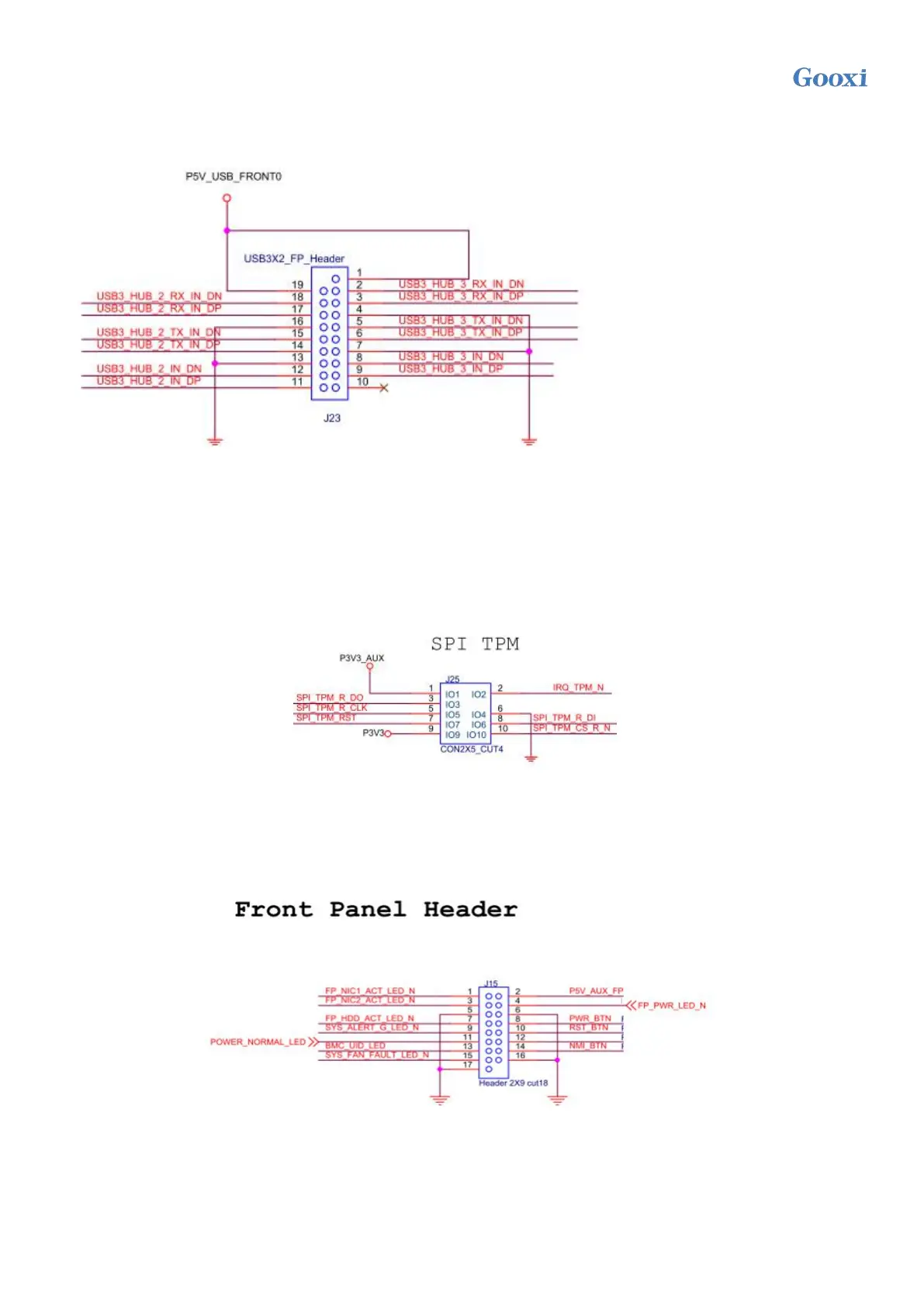
The side USB3.0 connector is a 2x10pin 2.0mm spacing fenced pin. The detailed signal definition is
as follows:
Figure 2-15
10) Front VGA connector
The motherboard provides a VGA interface that can be connected to the front panel to access the
VGA screen and output the host information.
11) SPI TPM expansion interface
The motherboard provides an SPI TPM expansion interface with 2x5pin NC pin4 2.54mm pin. The
detailed signal definitions are as follows:
Figure 2-16
12) Front panel connector/header
The front panel connector is a pin with a spacing of 2x9pin and 2mm (the 18th pin is empty). The
detailed signal definition is as follows:
Figure 2-17
14/15) Onboard power switch and restart button
The motherboard contains a system power switch and restart button.
16) Onboard USB3.0 connector
One USB3.0 interface is provided inside the motherboard.
 Loading...