Figure (3-5)
3.2. 3 Install memory
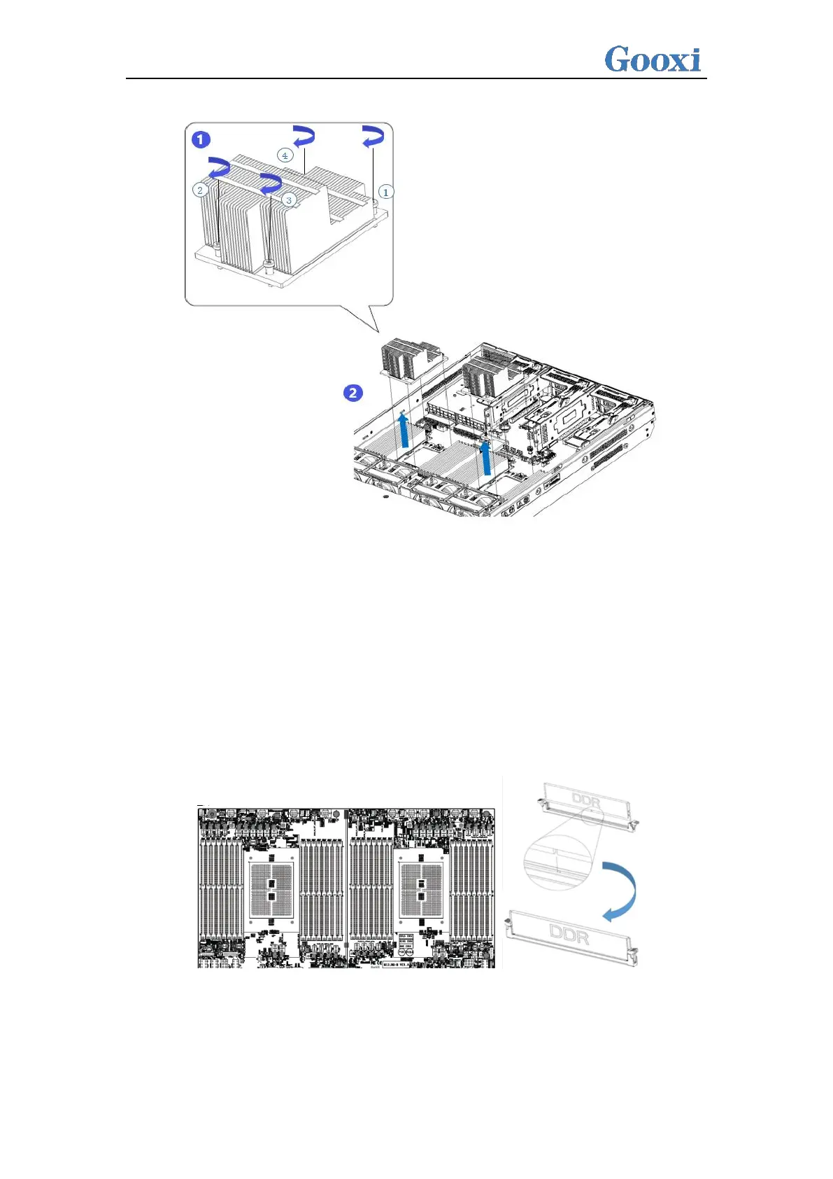
The 16 memory slots controlled by CPU 0 of the motherboard are: DIMMA1, A2, DIMMB1,
B2, DIMM C1, C2, DIMM D1, D2, DIMM E1, E2, DIMM F1, F2, DIMM G1, G2 and DIMM H1,
H2. The 16 memory slots controlled by CPU 1 are: DIMMA3, A4, DIMMB3, B4, DIMMC3, C4,
DIMMD3, D4, DIMM E3, E4, DIMM F3, F4, DIMM G3, G4 and DIMM H3, H4. Note that the
memory notches match the notches of the DIMM slots, and snap each DIMM module vertically
into place to prevent incorrect installation.
Figure (3-6)

 Loading...