4Working Principle
4.1 System Diagram
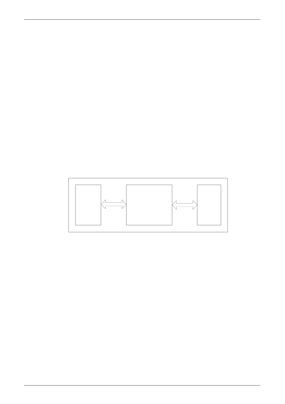
The UART Master IP acts as a "bridge." The main controller transmits
the command or data to the UART Master IP through synchronous SRAM
interface, and then the UART Master IP is sent to the UART Slave through
the UART; or uploads the UART Slave data to the main controller through
synchronous SRAM interface shown in Figure 4-1.
Figure 4-1 System Diagram
MCU UART Master
SRAM
Interface
UART
UART Slave
4.2 Gowin UART Master IP Register
Gowin UART Master IP has 8 registers:
Receive Buffer Register (RBR)
Transmit Holding Register (THR)
Interrupt Enable Register (IER)
Interrupt Identification Register (IIR)
Line Control Register (LCR)
Modem Control Register (MCR)
Line Status Register (LSR)
Modem Status Register (MSR)
Note!
The receive buffer register (RBR) and the transmit hold register (THR) have the same
address, both of which are 0x00.