4.3Gowin UART Slave Implementation
Delta Data Set Ready.
Change in DSRN after last MSR
read.
Delta Clear To Send.
Change in CTSN after last MSR
read.
Note!
The default value is X: indicates that this bit is driven by an external input signal.
4.3 Gowin UART Slave Implementation
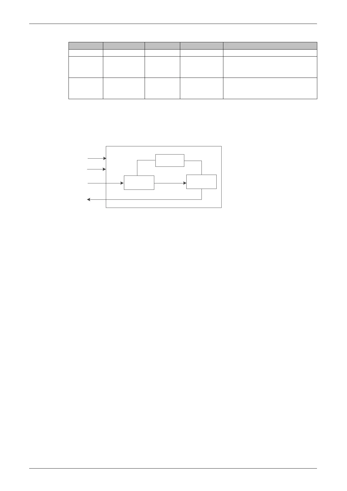
Figure4-10 UART Slave Implementation Block Diagram
Data
Reception
UART
Slave
rx
tx
Data Send
Parameter
Definition
sclk
rst_n
The UART Slave reference design mainly includes a data receiving
module and a data transmitting module. The data receiving module is
configured to receive the serial data sent by the Master and convert it into
parallel data transmission to the data sending module. The data sending
module receives the parallel data sent by the data receiving module and
converts it into serial data for transmission to the Master.
Parameter definitions are used to set the system clock frequency,
baud rate, and data frame format.