4.2Gowin UART Master IP Register
Request to send
1:Drive RTSn signal is
low
0:Drive RTSn signal is
high
The data terminal is ready
1:Drive DTRn signal is
low
0:Drive DTRn signal is
high
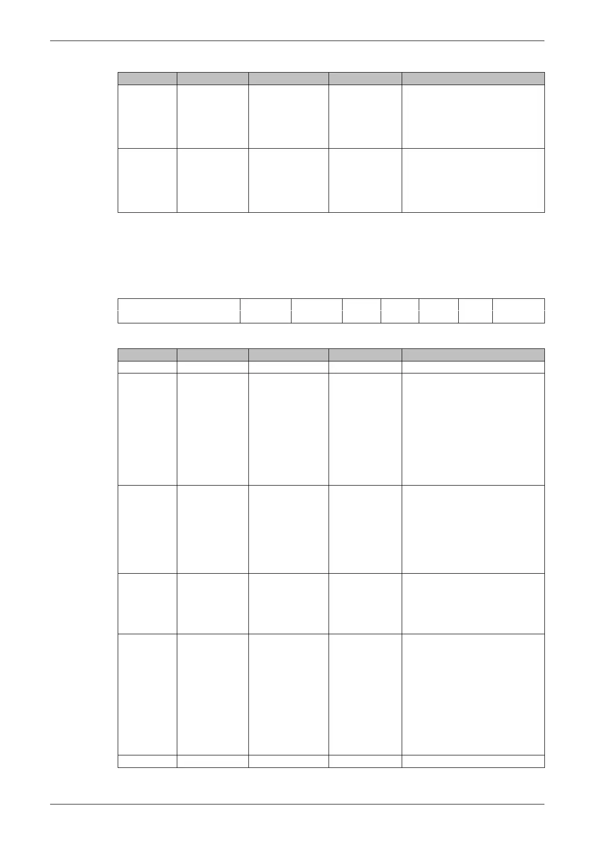
4.2.7 Line Status Register (LSR)
The line status register is shown in Figure4-8. The line status register
contains the current transmit and receive status. The bit definitions are
shown in Table4-8.
Figure4-8 Line Status Register
Table4-8 Line Status Register
Send empty
0:THR or Transmit
Shift Register contains
data
1:THR or Transmit
Shift Register is empty.
In FIFO mode, both
transmit FIFO and shift
register are empty.
Transmit Holding Register
(THR) is
0:THR or FIFO has
data to send
1:THR is empty. In
FIFO mode, the
transmit FIFO is empty.
Break Interrupt. Set this
interrupt when SIN is held
low for the entire data
transfer (start bit + data bit +
parity + stop bit)
Frame error. The
transmission loses a stop
bit. After the frame error, the
UART assumes that the
frame error is caused by the
start bit of the next
transmission. Try to
resynchronize by sampling
the start bit twice and
receiving the next data.