4.2Gowin UART Master IP Register
1:No interruption waiting
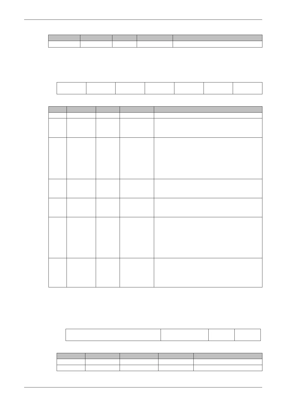
4.2.5 Line Control Register (LCR)
The line control register is shown in Figure4-6. The line control register
contains the serial communication configuration bits as defined in Table4-6.
Figure4-6 Line Control Register
Table4-6 Line Control Register
Setup interruption
1:Start interrupt
0:Disable interrupt
Forced parity
1: When the 3, 4 bits are logic 1, the
parity bit is transmitted and forced to logic
0; When bit 4 is logic 0 and bit 3 is logic 1,
the parity bit is transmitted and forced to
logic 1
0:Disable forced parity
Check selection
1:Select even parity
0:Select odd parity
Parity enable
1:Enable parity
0:Disable parity
Number of stop bits
0: 1 stop bit
1: 2 stop bits, select 1.5 stop bits when
transferring 5 data bits. The reception
only detects one stop bit and does not
care about the number of selected stop
bits.
Byte length selection
00: 5-bit data
01: 6-bit data
10: 7-bit data
11: 8-bit data
4.2.6 Modem Control Register (MCR)
The modem control register is shown in Figure4-7. The modem control
register contains the modem signal configuration bits. The bit definitions are
shown in Table4-7.
Figure4-7 Modem Control Register
Table4-7 Modem Control Register