Installation
14 3A6931A
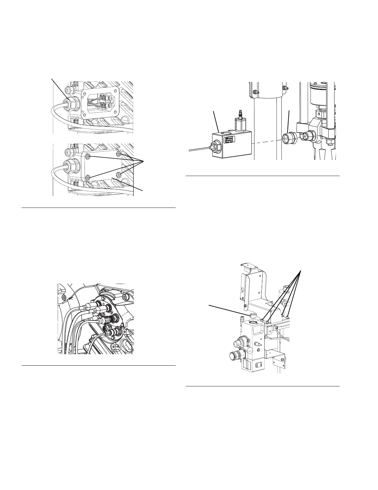
11. Install the new driver junction box cover using the
four screws. The cover and screws are included with
the cable track assembly.
12. Connect the cable track connections as shown in
Figure 15.
a. Connect the two CAN connectors to ports 1 and
2.
b. Connect the 5 pin connector to port 3.
c. Connect the 8 pin connector to port 4.
NOTE: Use Figure 3 on page 10 for further reference.
13. Use the shaft adapter included in the kit and
connect the electric driver to the pump coupling,
pump lower, and tie rods that were removed from
the air motor pump. Refer to the E-Flo SP Supply
Systems Installation-Parts manual. See Related
Manuals on page 2.
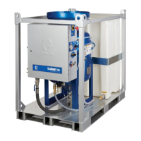
14. Connect the outlet check valve (102) using the
adapter fitting (104) included in the kit. Apply thread
sealant to the threads of the check valve and the
adapter fitting prior to installation. See Figure 16.
15. The pressure transducer cable from the outlet check
valve plugs into port 6 on the electric driver. Use
Figure 3 on page 10 for reference.
16. Use the wire ties (103) included in the kit to secure
the pressure transducer cable to a tie rod.
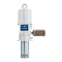
17. Mount the assembled ADM mounting brackets with
four screws (114) and washers (113) as shown in
Figure 17.
18. Plug the air line hole in the top of the air controls
with the supplied plug (134) as shown in Figure 17.
FIG. 14: D60 Driver Junction Box Cover
FIG. 15: D60 Cable Track Connections
FIG. 16: D60 Outlet Check Valve Installation
FIG. 17: D60 ADM Mounting Bracket