WPE
OF
PROBLEM
:ondition
B
(continued)
Both lamps
off
REFER
TO
THE WIR-
-.
~
PAGE 14 TO IDENTIFY
TP POINTS.
ING
DIAGRA~J
O
N
:ondition
C
Clear lamp off
Red lamps
on,
Unplug
sprayer!
WHAT TO
CHECK
If
check
is
OK.
00
to the next check.
1. Checkelectrical supply. Connectvoltmeter
to
electrical outlet. Meter should read
190-250
Volts
2.
Check power supply
to
circuit board with
sprayer turned
ON.
Measure voltage at
TP1 and TP2. Meter should read 190-250
Volts.
See page 26.
3.
Check all terminals and wires for damage
or loose
fit.
4.
Checkmotorthermalcutoutswitch..Unplug
sprayer. Allow motor
to
cool. Disconnect
TP10. Use ohmmeter
to
check continuity.
motor thermal switch leads at
TP9 and
cool.
Switch should be closed when motor
is
-.
5.
Check microswitch
(306).
With no fluio
pressure
in
the pressure control, discon
-
nect wires TPlSandTP19. Checkcontinu-
ity across switch terminals with an ohmrne-
press actuator button.
An
audible "clickin-
fer. Switch contact should be closed. De
-
dicates the contacts have opened. Ohm-
6.
Check circuit board (118) by substituting
with a aood board. See Daoe 26.
1.
Checkcircuit board
(1
18) by removing from
box withoutdisconnecting wires; see page
26 for removal procedure.
I
WHAT TO
DO
If
check
is
not
OK.
refer to this column.
1.
Reset circuit breaker or replace outlet
fuse.lf circuit breaker or fuse continues
to
open, see
"
Electrical Short
"
, page 18.
2. Unplug sprayer. Check continuity
of
both
polesofON/OFFswitch(302)fromTPlto
faulty.
TP2 and
TP2
to
TP3. Replace switch
if
Check continuity of
RFI
filter (310) from
TP4 to TP6 and TP3
to TP5. Replace filter
if
faulty.
Check power supply cord (31 1) for
conti-
nuitv from TP5 to TP7 and TP6
to
TP8.
Replace cord
if
faulty.
Check for any loose connections.
3. Replace damaged terminals and recon
-
nect securely.
4.
Replace electric motor
if
switch does
not
close when motor is cool. See page 35.
5.
Replace ihe microswitch. See page 23.
6. Replace circuit board. See page
26.
1. Replace circuit board. See page 26.
WARNING;
Removing the circuit board while still wired over
-
rides the
optical detector which could cause the sprayer to over
-
pressurize,
if
the
microswitch does
not
function properly. Turn the sprayer
on
ONLY long
enough
to
check lamp condition, then shut off immediately.
WARNING:
To reduce the risk of electric shock, handle board by edges
~
only!
Do
not allow any metal objects
to
come in contact with the board!
Plug in and turn
on
sprayer. Clear lamp
should be
on
now
-
removing the circuit
board over
-
rides the optical detector.
Turn
ofi
and unplug the sprayer.
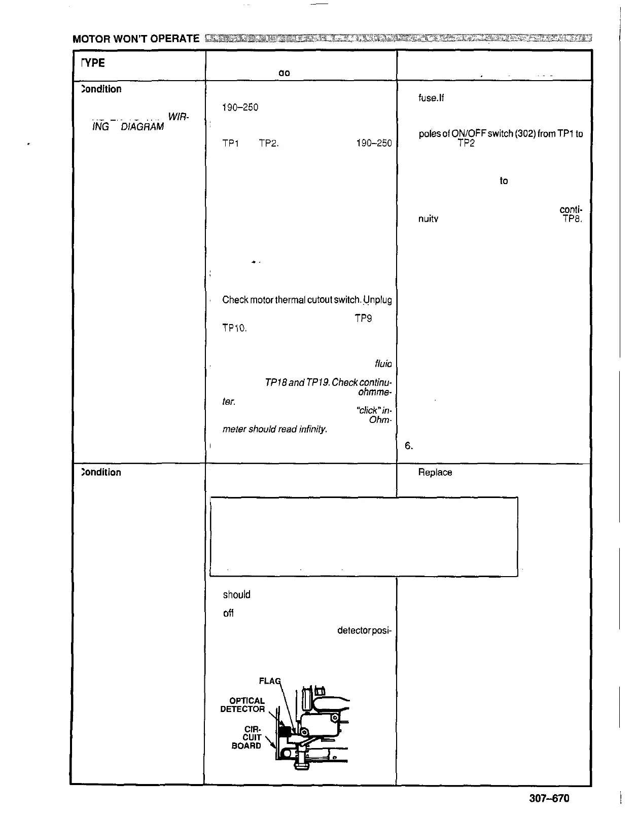
2. Check bourdon tube flag and
detectorposi-
tion. Reinstall circuit board (see page 26).
Turn pressure setting to maximum; flag
should extend less than half way into opti
-
cal detector
slot
from the bottom.
2. Calibrate pressure control to see
if
that
corrects problem. See page 28.
If
not, replace bare pressure control box
(301). See page
27.
307-670
15