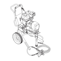
Alternator
Fig. 15
202
200
201
A
209
207
208
206
205
204
203
222
02728
202
204
201
205
206
207
209
B
222
CUTAWA
Y VIEW
B
D, 203
C
220
221
See
Fig. 12 for a detail of
where 206 connects
NOTE:
Refer to Fig. 15 which also shows the
assembly in a cutaway view
.
4.
Remove the screws (A) from the bushing (201)
and screw them into the threaded holes of the
bushing. T
ighten the screws until the sheave (202)
separates from the bushing. Remove these parts
and the key (200).
NOTE:
If necessary, use a steering wheel puller as
described in Step 6.b. on page 21.
5.
Remove the retaining ring (203).
6.
Press the shaft (B) of the alternator shaft rotor
(209) to free it from the clutch housing.
NOTE:
The bearing (204) must be replaced if you
remove the alternator rotor shaft (209).
7.
Remove the cable clamp (220) and screw (221).
8.
Remove the screws (207) and lockwashers (208)
and the stator (206).
9.
Remove the retaining ring (205).
10.
Remove the bearing (204) from inside the clutch
housing (222).
Reassembly
1.
Clean all parts.
2.
Reassemble in the reverse order of disassembly
.
Route the wires of the stator (206) through the
clutch housing (222) and through the hole (C) in
the mounting bracket. When pressing the shaft
(209) through the bearing (204), press it until the
groove D is exposed, then install the retaining ring
(203).
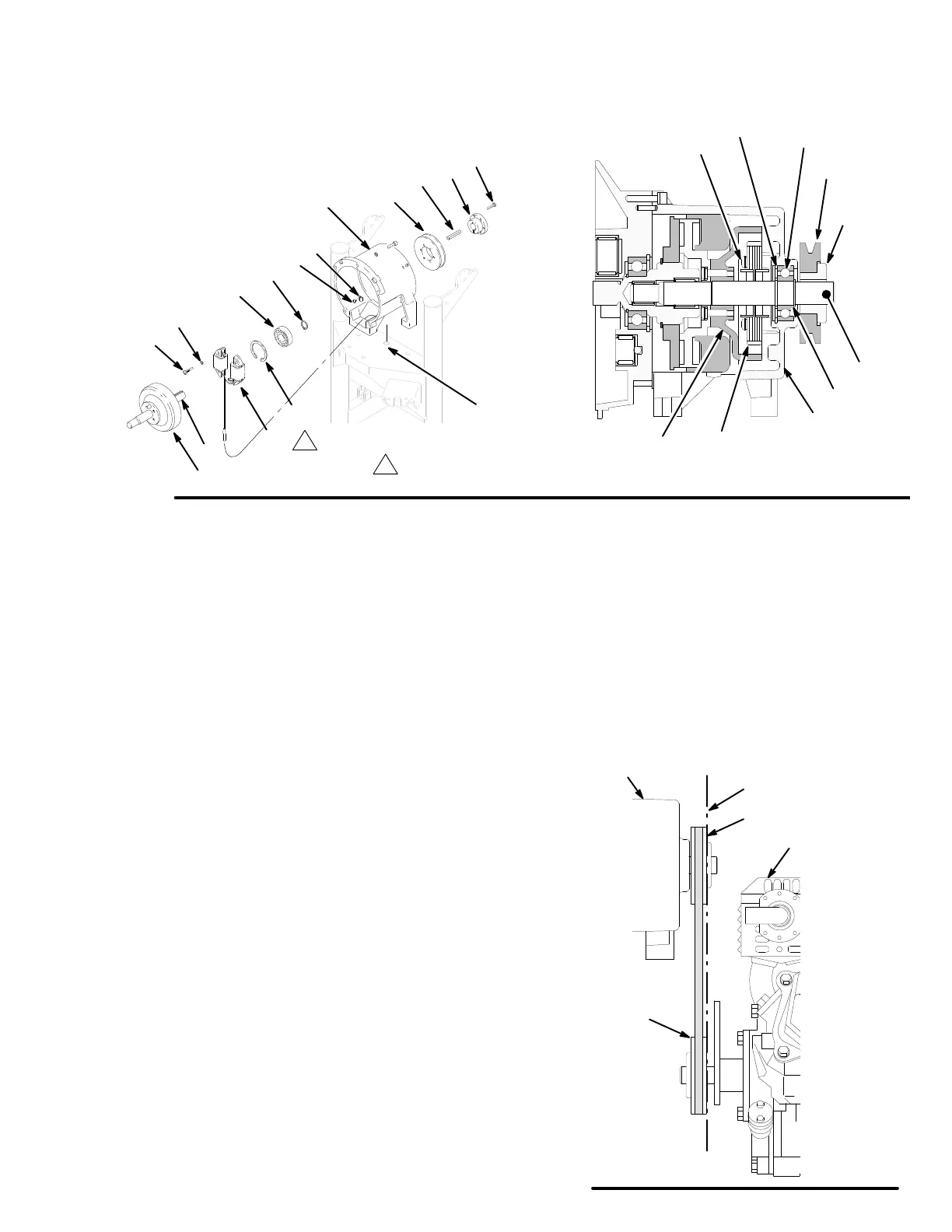
3.
Mount the engine or motor (1) without the belt
guard in place. Place a straight edge (E) along the
surfaces of the clutch pulley (202) and engine
pulley (41) as shown in Fig. 16 to be sure they are
vertically aligned. Readjust the bushing screws (A)
as needed to align the pulleys and recheck the
alignment.
Fig. 16
02747
202
41
1
E
222

 Loading...