Pinion
Remove the Pinion Housing
WARNING
To
reduce the risk of serious injury
, always follow
the
Pressure Relief Procedure W
arning
on page
16 before repairing the sprayer
.
NOTE:
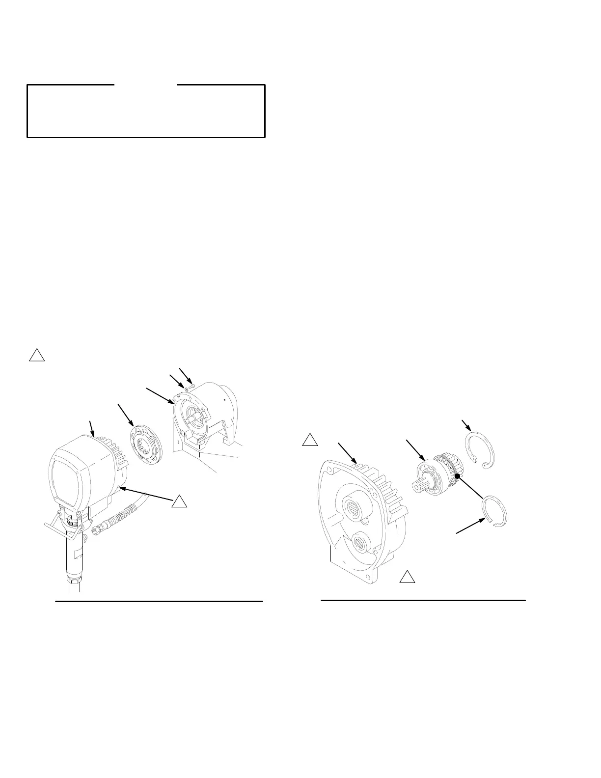
Refer to Fig. 8 for Steps 1 to 2.
1.
First remove the two bottom screws (3) and
lockwashers (4) from the clutch housing (222), and
then remove the top three screws and
lockwashers.
2.
Pull the pinion housing (219) away from the clutch
housing (222). The armature (212b) will come out
still attached to the clutch housing. Pull the arma
-
ture of
f the hub inside the pinion housing.
NOTE:
T
o disassemble the pinion, go to
Repairing
the Pinion. T
o disassemble more of the sprayer
, go to
page 21. T
o reassemble the sprayer from this point,
skip ahead to
Reassembly
, page 24, Steps 3 and 4.
Fig. 8
02695
219
212b
222
See
Fig. 9
4
3
Repairing the Pinion
NOTE:
Repair Kit No. 236–394
includes the shaft and
bearings pre-assembled and lubricated. A hydraulic
press is not required. Use the repair procedure below
.
NOTE: If purchasing the pinion parts separately,
the repair must be done by a qualified technician since
parts must be press fit. Refer to the parts drawing on
page 38.
NOTE:
Refer to Fig. 9 except where noted.
1.
Remove the retaining ring (218e).
2.
Remove the large ring (217) from the bearing re
-
cess of the pinion housing (219).
3.
Pull the the pinion output shaft (218) out of the
housing (219).
4.
Install the new pinion output shaft (218) into the
pinion housing, pushing it to the shoulder of the
housing (219).
5.
Install the rings (218e and 217).
6.
Go to
Reassembly
, page 24, Steps 3 and 4, or
continue on page 21.
Fig. 9
219
218
217
02787
Drive
housing shown
removed for visual
purposes only
218e

 Loading...


