26
308-327
Pressure
Control Replacement
WARNING
To
reduce the risk of serious injury
, always follow
the
Pressure Relief Procedure W
arning
on page
16 before repairing the sprayer
.
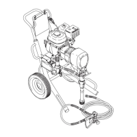
Fig. 19
02703
Front view
63
317
318
Note
the original location
of these hoses.
1. Relieve
pressure.
2.
Disconnect the hoses (63) while holding the el
-
bows (318) firmly
. See the
CAUTION
, below
. Note
the original location of each hose to be sure you
reassemble them correctly
. See Fig. 19.
CAUTION
DO NOT allow the nipple (317) to turn when re
-
moving or connecting the hoses. T
urning the el
-
bows can damage the bourdon tube.
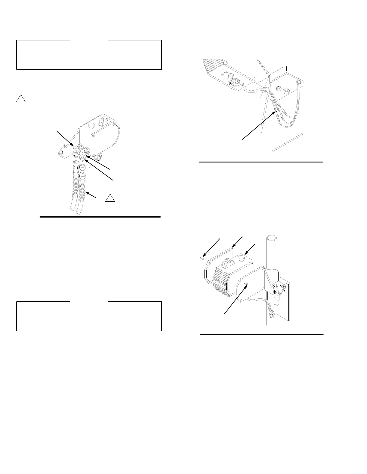
3. W
orking under the cart, disconnect the wires (A).
See Fig. 20.
Fig. 20
02700
A
4.
Remove the pressure control screws (67) and
cover (70). See Fig. 21.
5.
Remove the screws (67) from the back mounting
bracket (76) and remove the pressure control (74).
See Fig. 21.
Fig. 21
02704
Rear view
70
74
67
67

 Loading...