Pressure
Control Adjustment
WARNING
USE
EXTREME CAUTION WHEN PERFORMING
THIS CALIBRA
TION PROCEDURE
to reduce the
risk of a fluid injection injury or other serious bodily
injury
, which can result from component rupture,
electric shock, fire, explosion or moving parts.
This procedure sets the sprayer to 2600–3000 psi
(182–210 bar) MAXIMUM WORKING PRESSURE.
This procedure must be performed whenever the
pressure control assembly is removed and rein
-
stalled, or replaced, to be sure the sprayer is
properly calibrated.
Improper calibration can cause the sprayer to
over–pressurize and result in component rupture, fire
or explosion. It may also prevent the sprayer from
obtaining the maximum working pressure,
resulting in poor sprayer performance.
NEVER attempt to increase the fluid outlet pressure
by performing these calibrations in any other way
.
NEVER EXCEED 3000 psi (210 bar) MAXIMUM
WORKING PRESSURE. Normal operation of the
sprayer at higher pressures could result in compo
-
nent rupture, fire or explosion.
ALWA
YS use a
new
50 foot (15.2 m) spray hose,
rated for at least 3000 psi (210 bar) MAXIMUM
WORKING PRESSURE, when performing this
procedure. A used, under–rated hose could
develop a high pressure leak or rupture.
A
VOID touching the wires in the pressure control as
-
sembly when the control box cover is removed, to
reduce the risk of electric shock.
Service Tools Needed:
NEW
50 foot (15.2 m), 3000 psi (210 bar), flexible
nylon, airless spray hose, p/n 223–541
0–5000 psi (0–350 bar) fluid-filled pressure gauge,
p/n 102–814
NEW
spray tip, size 0.025 to 0.029
3/8 in. ignition wrench or nut driver
5 gallon pail and water or mineral spirits
Swivel, p/n 156–823
Nipple, p/n 162–453
T
ee, p/n 104–984
Set Up
WARNING
To
reduce the risk of serious injury
, always follow
the
Pressure Relief Procedure W
arning
on page
16 before repairing the sprayer
.
1.
Relieve pressure.
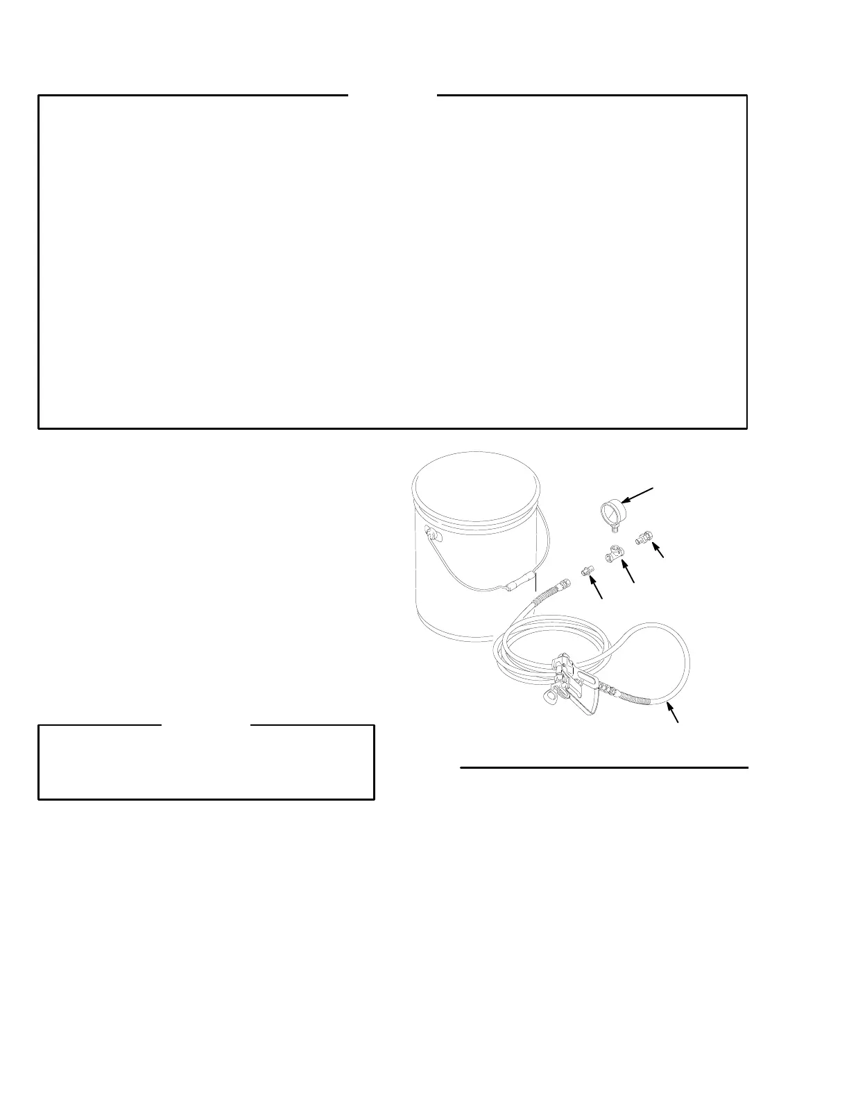
2.
Remove the original spray hose. Assemble and
install the components shown in Fig. 23 to the fluid
filter outlet.
Fig. 23
01201
102–814
156–823
104–984
162–453
223–541

 Loading...


