Pressure
Control Replacement
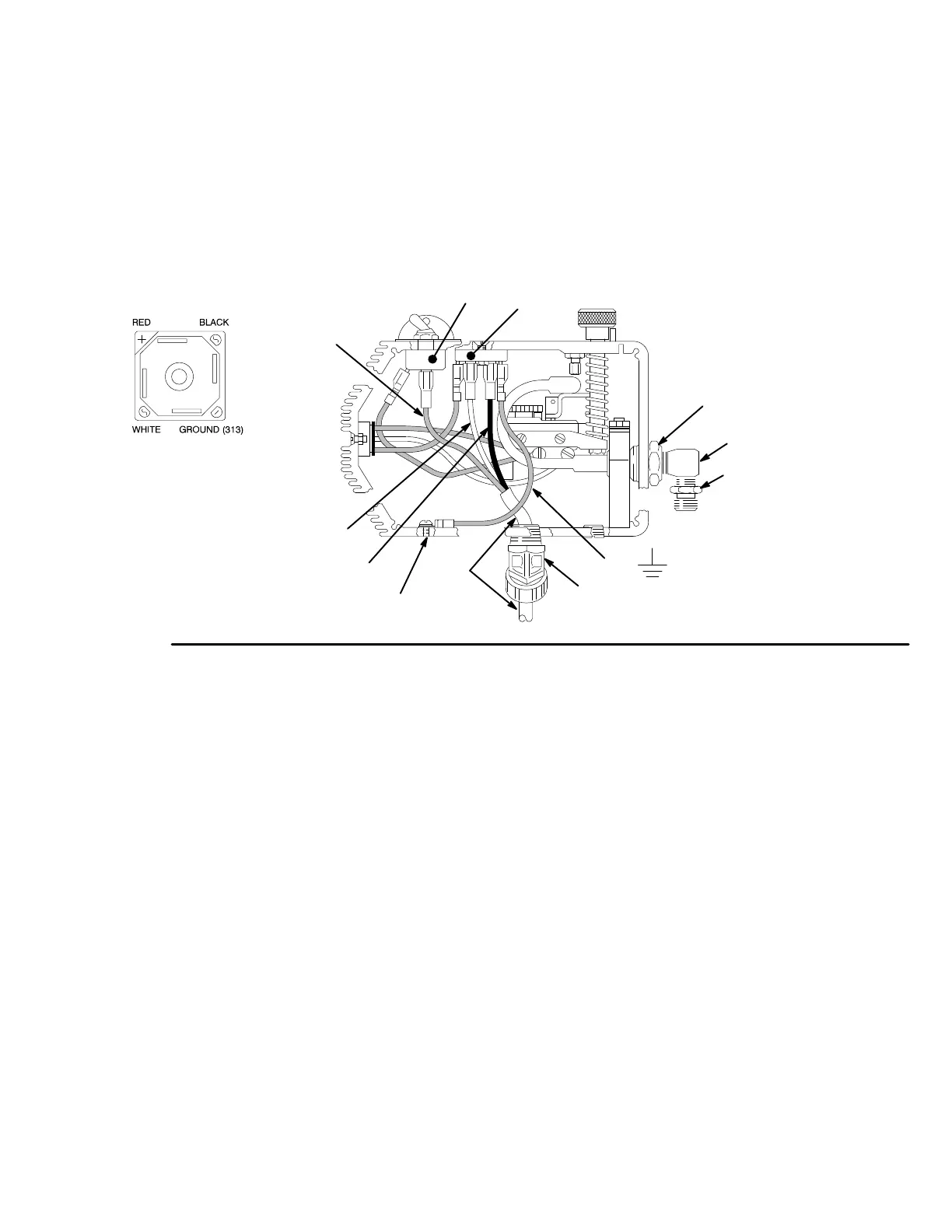
6. Disconnect
the black, red and white wires from the
rectifier (307) and switch (302), which are
sheathed with the conductor (316). See Fig. 22.
7.
Unscrew the connector (319) from the control box,
pulling the conductor and wires out with it.
8.
Remove the nipple (317) from the elbow (318).
See Fig. 22.
9.
Use a wrench to hold the hex of the adapters (A)
while removing the elbows (318).
10.
Reassemble in the reverse order
.
11.
Perform the
Pressure Control Adjustment
on
page 28 before regular operation of the sprayer
.
317
h
318
BLACK
WHITE
314,305
319
RED
Fig. 22
307
313
316
0151
A
302
Rectifier (307)
Connections

 Loading...