Field
and W
iring Harness
Fig.
1
1
02702
A
22
64
211
210
See
Fig 12 for a detail of
where 64 connects
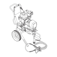
NOTE:
Refer to Fig. 1
1.
1.
Pull the plastic caps (A) of
f the wire screws (22) in
both places on the field. Loosen the screws and
release the wires (64).
2.
Loosen the four setscrews (21
1). Pull of
f the field
(210).
3.
Skip ahead to
Reassembly
,
page 24, Step 1 or
continue on page 22.
Fig. 12
02700
Ref 64
Ref 206
Alternator
Fig. 13
02689
B
A
95
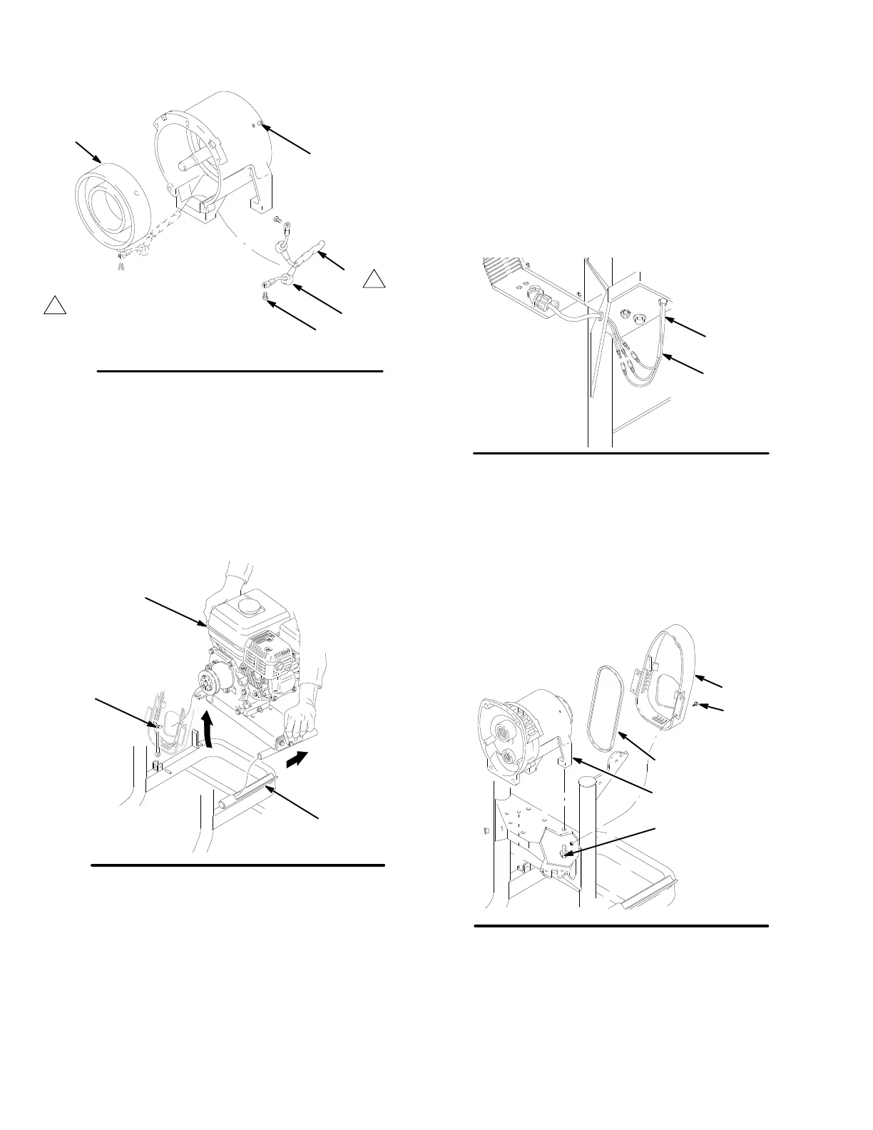
Disassembly
1.
Remove the engine. Loosen the knob (95). Grasp
the engine as shown in Fig. 13 and raise side A.
Slide the engine out of the channel (B).
2.
Remove the screws (43) and belt guard (35).
Remove the belt (40). See Fig. 14.
Fig. 14
100
222
40
43
35
3.
Remove the clutch housing (222) by removing
screws (100) from below the cart. See Fig. 14.
NOTE:
This procedure is continued on page 23.

 Loading...