Repair
3A1570V 35
Check FTS Cables
1. Turn main power OFF . Disconnect power
supply.
2. Follow the Pressure Relief Procedure, page 15.
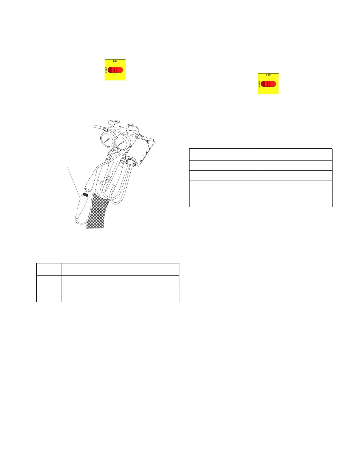
3. Disconnect FTS cable (F) at Reactor, F
IG
. 11.
4. Test with ohmmeter between pins of cable
connector.
5. If cable fails test, retest at FTS. See Test/Removal,
page 35.
Fluid Temperature Sensor (FTS)
Test/Removal
1. Turn main power OFF . Disconnect power
supply.
2. Follow the Pressure Relief Procedure, page 15.
3. Remove tape and protective covering from FTS.
Disconnect hose cable (F). Test with ohmmeter
between pins of cable connector.
4. If FTS fails any test, replace FTS.
5. Disconnect air hoses (C, L), and electrical
connectors (D).
6. Disconnect FTS from whip hose (W) and fluid hoses
(A, B).
7. Remove ground wire (K) from ground screw on
underside of FTS.
8. Remove FTS probe (H) from component A (ISO)
side of hose.
Installation
The Fluid Temperature Sensor (FTS) is supplied. Install
FTS between main hose and whip hose. See Heated
Hose manual 309572 for instructions.
F
IG
. 11. Heated Hose
Pins Result
1 to 2 approximately 35 ohms per 50 ft (15.2 m) of
hose, plus approximately 10 ohms for FTS
1 to 3 infinity
Pins Result
1 to 2 approximately 10 ohms
1 to 3 infinity
3 to FTS groundscrew 0 ohms
1 to FTS component A
fitting (ISO)
infinity