Setup
20 3A2776K
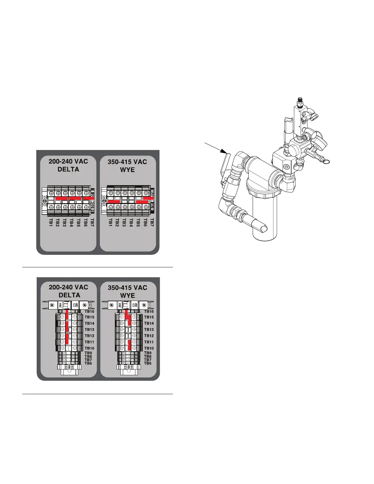
Set Power Jumpers
1. Find the red power jumpers for the terminal blocks
supplied in a plastic bag in the circuit box. For
hazardous location models, are in the explosion
proof box (E1).
2. For 200-240 VAC and 350-415 VAC, 3 Phase
installations only, use pliers to install the three red
power jumpers into the terminal blocks in the correct
positions as shown in the following illustration. Push
jumpers firmly into position.
3. Close junction box cover.
Connect Air Supply
Connect air supply line to the 1 in. npt(f) air supply ball
valve inlet.
Use a 3/4 in. (19.1 mm) ID minimum air hose.
Air supply requirement: 150 psi (1.0 MPa, 10.3 bar)
maximum; 80 psi (552 kPa, 5.5 bar) minimum (while
running).
Flow volume required: 100 scfm (2.8 m
3
/min) minimum;
250 scfm (7.1 m
3
/min) maximum. Available fluid
pressure and flow rate are directly related to available
air volume. A typical single gun XM PFP application will
use 125 to 175 scfm (3.5 to 5.0 m
3
/min).
Dosing valves are operated by air. The sprayer will not
operate correctly if the inlet air pressure drops below
80 psi (552 kPa, 5.5 bar) while spraying.
FIG. 12: Non-Hazardous Location Models
FIG. 13: Hazardous Location Models
 Loading...