Troubleshooting Information
3A2776K 63
Individual Control Module LED Diagnostic Information
The following LED signals, diagnosis, and solutions are the same for the display module, advanced fluid control
module (AFCM), fluid control cube, high power temperature control module (HPTCM), and USB module. LEDs are
located next to the module power cable.
Troubleshooting
NOTE: Pressure Relief Procedure on page 46 before
servicing the system.
NOTE: The sprayer operates using air pressure. Many
problems are caused by inadequate air supply. The inlet
air pressure gauge cannot drop below 80 psi (0.5 MPa,
5.5 bar) while running.
Module Status LED Signal Diagnosis Solution
Green on System is powered up and power
supply voltage is greater than
11 Vdc.
---
Blue
(HPTCM only)
Voltage is being sent to the heater ---
Yellow Internal communication in progress ---
Red solid Hardware failure Replace module.
Red flashing fast Uploading software ---
Red flashing slow Token error Remove token and upload software
token again.
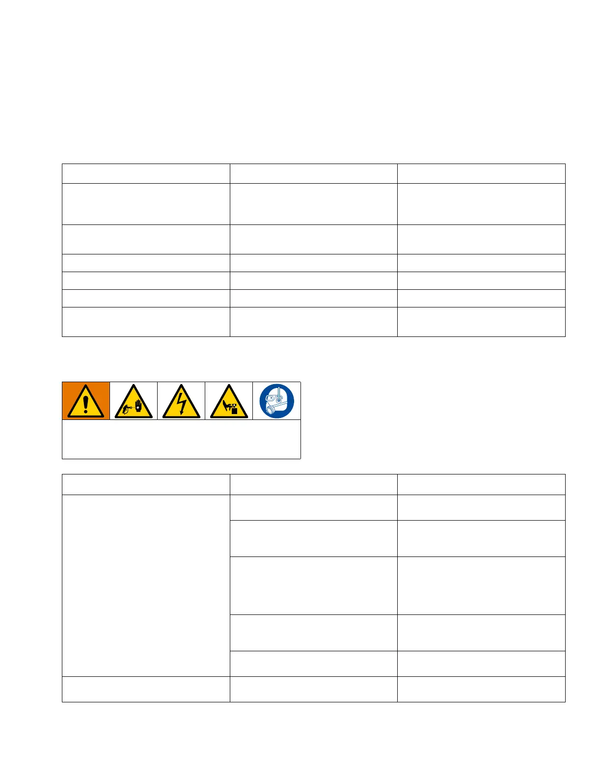
All electrical wiring must be done by a qualified
electrician and comply with all local codes and
regulations.
Problem Cause Solution
Display not lit. No green light present on
back of display module.
No electric power. Disconnect “off” or
breaker “open.”
Reset main disconnect and breaker.
Voltage jumpers not installed or config-
ured in power junction box.
Install red jumpers in junction box termi-
nal blocks. See Connect Power Cord on
page 19.
No green lights present on display, FCM,
or USB module.
Check for 24 Vdc on J1, pins 2 and 3, of
power supply. See Electrical Schematics
in the XM PFP repair manual. If there is
not 24 Vdc, replace power supply mod-
ule. See XM PFP repair manual.
No display power through CAN cable.
Green light in present on AFCM, but is
not present on USB module.
Check CAN cable. Replace if necessary.
See the XM PFP repair manual.
Green light is present on USB module. Check CAN cable. Replace if necessary.
See the XM PFP repair manual.
Display not lit on system. Green light is
present on back of display module.
Display module failed. Replace display module. See the XM
PFP repair manual.
 Loading...