Section 10: Commissioning Page 37
10.2 BURNER SETTINGS:
RDB2.2 BX BURNERS
FOR 15-26 AND 26-46 MODELS
With the burner removed from the boiler:
1. Unscrew and remove the two screws holding the air intake
spigot to the top of the air inlet cover.
2. Remove and discard the air intake spigot and gasket.
3. Fit the slotted air intake (provided loose with the boiler) to the
top of the air intake cover and secure using one of the two
screws previously removed.
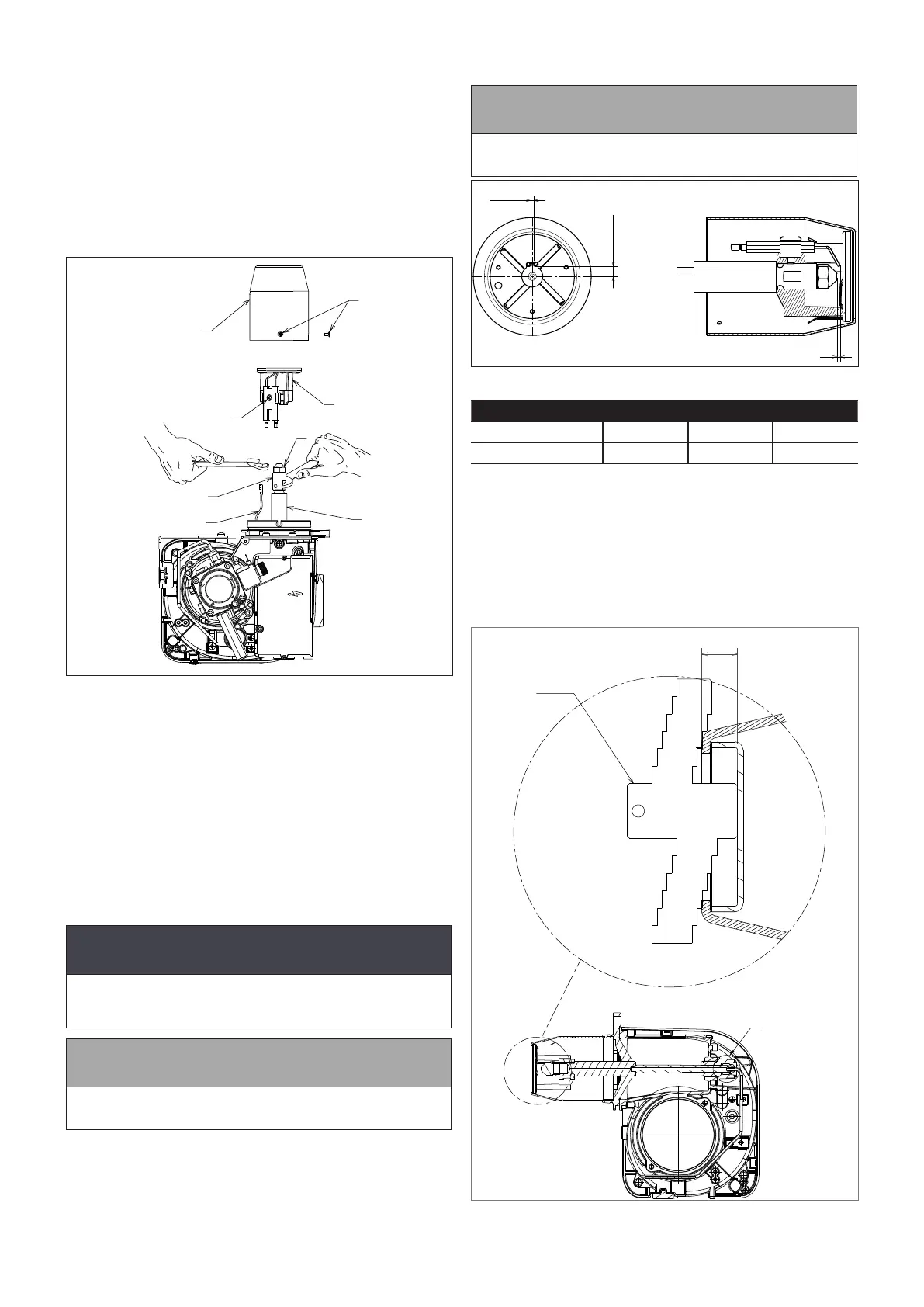
4. Remove the burner head. Refer to Figure 10-5. Loosen the
three xing screws (1) and remove head (2) from burner.
7
4
6
8
5
3
1
2
Figure 10-5: Burner head, recirculation tube (if tted) diuser and
nozzle holder
5. Check the nozzle is correct for the required boiler output.
Refer to Table 2-2 for the correct nozzle size and type for the
required boiler output.
6. If the nozzle needs to be replaced - remove the diuser/
electrode assembly. Refer to Figure 10-5.
• Using a 4 mm Allen key, loosen the diuser xing screw
(3) on the electrode assembly.
• Lift diuser/electrode assembly (5) up and o the nozzle
holder.
• Disconnect both ignition leads (4) from the electrodes.
7. Use a 16 mm spanner to remove/re-t the nozzle, whilst
holding the nozzle holder using a 19 mm spanner.
! CAUTION !
The use of an ill-tting spanner will damage the nozzle
and could lead to an incorrect ame pattern and poor
combustion.
! NOTE !
Ensure that the nozzle is securely tightened so that it does
not leak but DO NOT OVER TIGHTEN!
8. Re-t the diuser/electrode assembly. Refer to Figure 10-5.
• Reconnect ignition leads (4) to electrodes.
• Re-t the diuser/electrode assembly (5) onto the nozzle
holder lining up the xing screw with the recess in the
nozzle holder.
• Ensure diuser assembly is tted down hard onto the
shoulder on the nozzle holder.
• Tighten the xing screw (3) to secure the diuser/
electrode assembly in place on the nozzle holder.
! NOTE !
Do not overtighten the xing screw as this may damage
the electrode insulator.
±0.5
A
±0.3
B
C
Figure 10-6: Ignition electrode settings
Model A B C
15-26 7 2.5 2.5 - 3
26-46 4.5 3 2 - 2.5
9. Check/adjust electrode setting. Refer to Figure 10-6.
10. Re-t the burner head. Refer to Figure 10-5.
• Locate the head xing screws (1) in the countersunk
slots in the burner collar.
• Check that the small oil drip hole (on the head) is
pointing downwards.
• Tighten the three screws (1) to secure the head (2) in
position on the burner.
11. Adjust the diuser position. Refer to Figure 10-7.
Figure 10-7: Riello RDB 2.2 BX diuser position and gauge plate