Section 7: Sealed Systems Page 21
All Grant Vortex Boiler House models are suitable for use with
sealed systems complying with the requirements of BS EN 12828,
BS EN 12831 and BS EN 14336.
The system must be provided with the following items:
• Diaphragm expansion vessel complying with BS EN 13831
• Pressure gauge
• Pressure relief (safety) valve
• Approved method for lling the system
7.1.1 EXPANSION VESSEL
The expansion vessel should be tted in the return pipework
as shown in Figure 7-1. To reduce the operating temperature
of the expansion vessel, position it below the pipe to which it is
connected.
The expansion vessel may be positioned away from the system,
providing the connecting pipe is not less than 13 mm in diameter.
If the expansion vessel is connected via a exible hose, care must
be taken to ensure that the hose is not twisted or kinked.
7.1 SEALED SYSTEM REQUIREMENTS
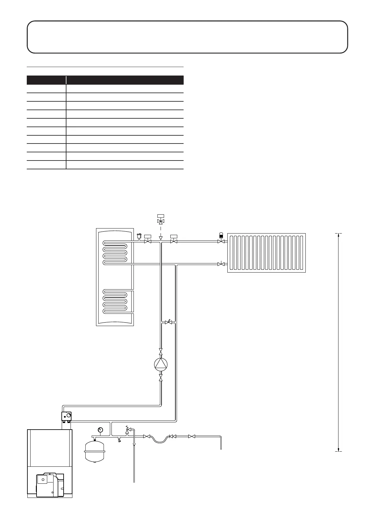
Table 7-1: Key to sealed system diagram
Key
1 Expansion vessel
2 Pressure gauge
3 Pressure relief valve
4 Tundish
5 Removable lling loop
6 Double check valve
7 Air vent
8 Thermostatic radiator valve
9 Automatic bypass
10 Drain point
Figure 7-1: Sealed system
7 SEALED SYSTEMS
Highest point of primary circuit
Centre of expansion vessel

 Loading...


