9.3 CONNECTING A CONVENTIONAL FLUE
If the Grant ‘Orange’ ue system is being used – follow the
instructions supplied with the ue kit.
If the Grant ‘Hybrid’ system, utilising components from the Grant
Green and Orange ue systems, is to be tted to the boiler then
the Grant CF adaptor kit (product code: CFA15/70) must be used
– refer to both Section 1.3 and Figure 9-4.
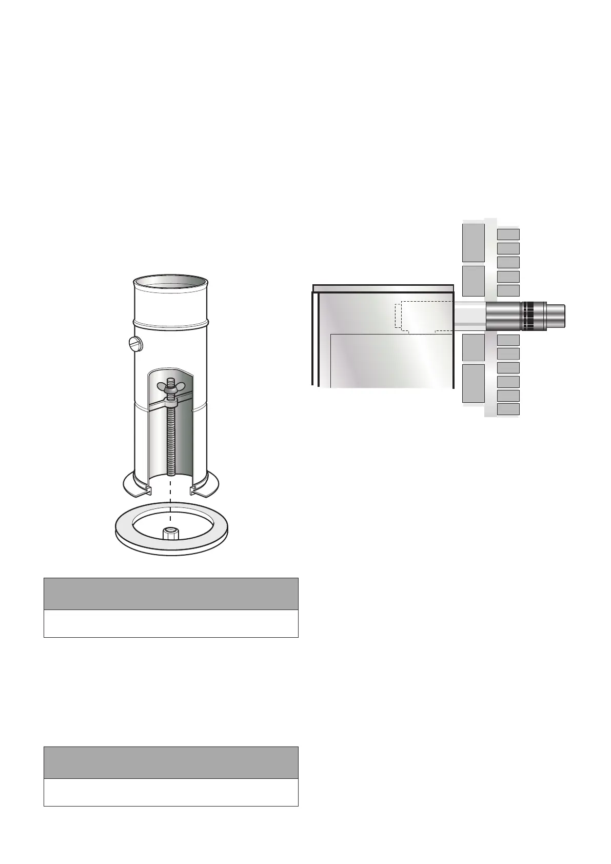
To t the adaptor kit, proceed as follows:
1. Fully screw the length of threaded studding (provided in the
kit) into the nut located in the centre of the boiler ue outlet.
2. Fit the boiler connector (from the CF adaptor kit) over the
threaded studding.
3. Position ange on to the neoprene gasket around the boiler
ue outlet, ensuring that small spigot on the base of the
connector is located in the hole in the centre of the neoprene
gasket and that end of studding passes through the hole in
the of the spacer bracket.
4. Fit washer and wing nut provided onto the end of threaded
studding and secure connector in position by tightening down
on wing nut – as shown in Figure 9-5.
5. Fit the ue adaptor (from the adaptor kit) into the boiler
connector.
Figure 9-5: Boiler ue connector
! NOTE !
Lubricate the seal on the adaptor using the lubricant
provided before attempting to t the ue adaptor.
6. Fit the rst section of ue into the ue adaptor and secure
using the clamp band provided.
7. Assemble the remainder of the ue system as required,
lubricating the seal on each component before tting.
9.4 BALANCED FLUE SYSTEMS
Apart from a conventional ue, several balanced ue options are
available for use with the Grant Vortex boilers.
All are suitable for use with Class C2 Kerosene.
! NOTE !
None of the ue sections in the following system can be cut.
LOW LEVEL HORIZONTAL BALANCED FLUE
(YELLOW SYSTEM)
Available in Short (for single thickness brick walls) and Standard
kits.
Extensions are available which extend the ue by 225 mm, 450
mm or 675 mm. (For internal use only).
90° and 45° elbows are also available. (For internal use only).
The maximum ue length - from the centre of the boiler ue outlet
to the outer face of the wall - is 4 metres (with or without elbows
included).
No more than 2 x 45 or 1 x 90 elbow should be tted per system.
The low level balanced ue (Yellow system) is supplied with a
stainless steel guard. This must be tted in all circumstances to
prevent objects from entering the ue outlet.
The guard must be tted centrally over the ue terminal and
securely xed to the wall.
Figure 9-6: Low level balanced ue
PLUME DIVERTER KIT FOR LOW LEVEL
BALANCED FLUE (YELLOW SYSTEM)
Should the low level balanced ue supplied with the boiler be
discovered to cause a plume nuisance after its installation, a
plume diverter kit is available to purchase from Grant UK for the
purpose of re-directing the ue gases to a higher level (according
to the minimum clearances shown in Figure 9-13).
The plume diverter kit has been designed to be retrotted to an
existing yellow system low level balanced ue by attaching directly
to the low level terminal supplied with the boiler.
This kit is available in two sizes, product codes as follows:
• GDPA90B - suitable for installations of up to 26kW (maximum
vertical length of 2.08m)
• GDPA200B - suitable for installations ranging from 26-70kW.
(maximum vertical length of 2.14m)
While every eort has been made to make this retrot as simple
as possible for the installer, it is necessary for the installer to drill
an 8mm hole in the side of the existing ue terminal to ensure
that the condensate produced by the ue gases during normal
operation drain back into the boiler.
It is also necessary for the installer to spot drill two 3mm holes in
the existing ue terminal. With the plume diverter starter elbow
in its nal position on the existing ue terminal, use the holes in
either side of this elbow as a guide to drill the two holes in the
terminal and x the elbow to the existing terminal by driving one of
the two self-tapping screws provided into each hole.
More detailed installation instructions for this system can be found
in the tting instructions supplied with the kit.
Please see Figure 9-7 for a visual representation of the contents
of the plume diverter kit.
A series of extensions and other accesories are available for use
with this kit. Please contact Grant UK for further information.
Section 9: Flue System and Air Supply Page 29