To ensure safe and ecient operation, it is essential that a Grant
Vortex boiler is commissioned as detailed in the following section.
10.1 BEFORE SWITCHING ON
Ensure the boiler is isolated from the electrical supply that all
system controls are set to OFF.
THERMOSTATS
1. Check that both the high limit thermostat and control
thermostat phials are correctly located in their respective
pockets. Refer to Figures 5-4, 5-5 or 5-6 as required.
2. Check the condition of both thermostat capillaries; that they
are not damaged, broken, kinked or crushed.
HEAT EXCHANGER
Check the baes and spiral turbulators.
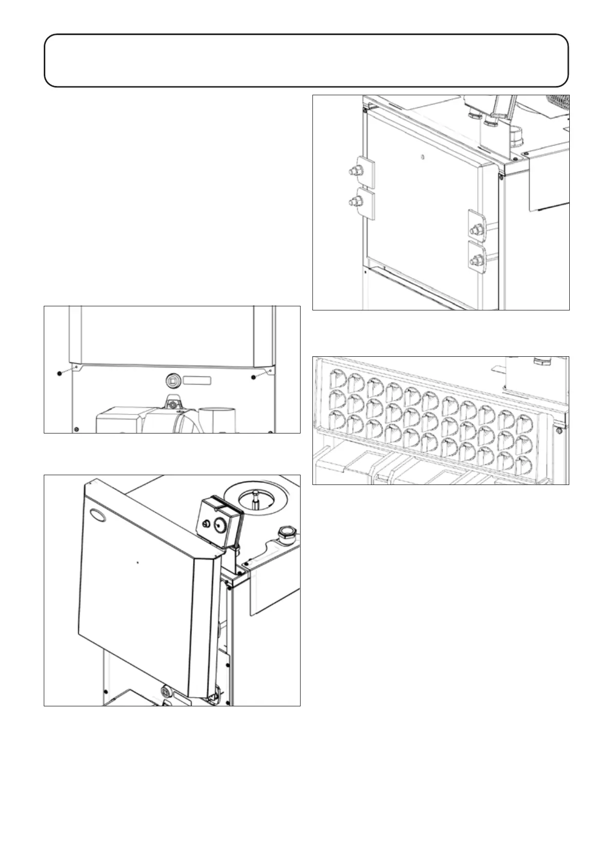
1. To access these rst remove the upper front panel. Unscrew
and remove the two screws located on either side of the
panel, just below the overhang. Refer to Figure 10-1.
2. Lift the upper front panel up and o the boiler. Refer to Figure
10-2.
3. Unscrew and remove the nuts and washers securing the
front cleaning door. Remove the door from the boiler - take
care as it is HEAVY! Refer to Figure 10-3.
4. Check that all the spiral turbulators are in position and that all
the ends are vertical. Refer to Figure 10-4.
5. Check that the baes are in position. Refer to Figures 11-
1,11-2 and 11-3 as required.
6. Re-t the cleaning door and check it is tted correctly and
that a good seal is made.
7. Replace the upper front panel and secure using the two
screws previously removed.
BURNER
1. Unscrew the burner xing nut (located at the top of the
mounitng ange) and remove the burner from the boiler.
2. Check/adjust the burner sttings as described in Sections 10.2
or 10.3.
3. Re-t the burner to the boiler and tighten the xing nut. DO
NOT OVERTIGHTEN!
HEATING SYSTEM
1. Check that the water system has been vented (and
pressurised if sealed system) and there are no leaks.
2. Check that all system controls are calling for heat and turn
the boiler thermostat to maximum.
AIR SUPPLY
1. Ensure the exible air tube is connected to both the burner
and ue system (on balanced ue models only).
2. Check that the boiler has a sucient permanent air supply.
Refer to Section 9.1.
Section 10: CommissioningPage 36
10 COMMISSIONING
Figure 10-1: Removing the two screws (15-26 model shown)
Figure 10-2: Removing upper front panel (15-26 model shown)
Figure 10-3: Front cleaning door (26-46 model shown)
Figure 10-4: Spiral turbulators (26-46 shown)