Section 9: Flue System and Air SupplyPage 26
9.1 AIR SUPPLY
A sucient permanent air supply to the boiler should be provided
for the following reasons:
• For proper combustion of fuel and eective discharge of
combustion products to the open air.
• For the ventilation of any conned space in which the boiler
is installed to prevent overheating of the boiler and any
equipment in and near the boiler.
It is essential to ensure that any ventilation openings in the
property are positioned to avoid accidental blockage and also
to minimise discomfort caused to the building occupants by
draughts.
Further details may be obtained from BS 5410-1.
! NOTE !
For a boiler tted in a compartment, which is ventilated as
shown, no additional allowance is necessary.
Open ue - Extract fans, where needed, should be in accordance
with Section 5.4.7 in BS 5410-1.
All ventilation areas given are for domestic applications and relate
to the full output rating of the boiler.
For installations in older dwellings (constructed prior to the
introduction of Approved Document L1A 2006) the rst 5 kW of
output can be ignored. For all other cases refer to BS 5410-2.
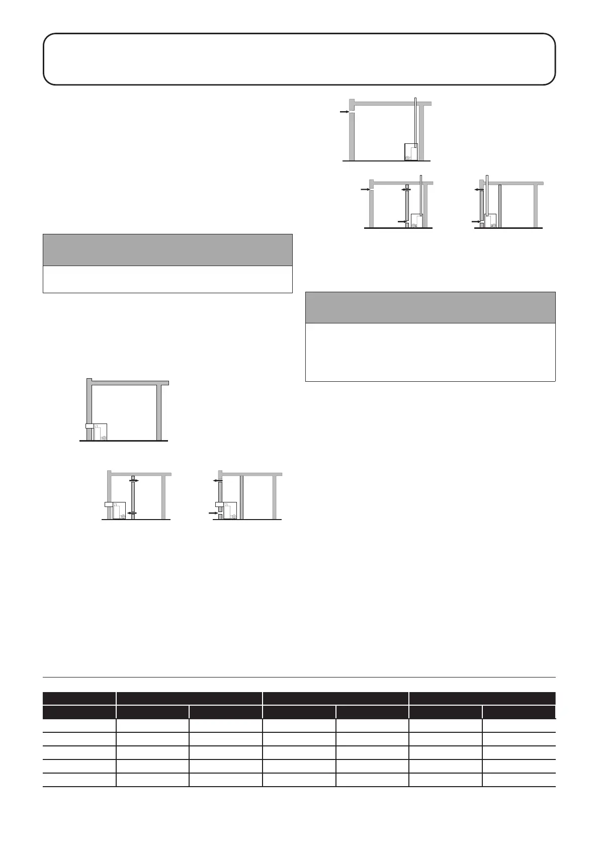
Room sealed balanced flue
no ventilation required to room
Room sealed balanced flue
compartment ventilated from room
Room sealed balanced flue
compartment ventilated from outside
B
B
A
A
Figure 9-1: Air supply for room sealed balanced ue boilers
IN
Conventional open flue
C
BOILER IN
COMPARTMENT
Conventional open flue
compartment ventilated from room
Conventional open flue
compartment ventilated from
C
C
D
D
E
Figure 9-2: Air supply for conventional ue boilers
9.2 CONVENTIONAL FLUE SYSTEMS
! NOTE !
Under no circumstances can Grant Vortex boilers be
installed with existing ue systems. Only ue systems and
components suitable for wet ues should be used.
Failure to install the correct type of ue system will
invalidate the guarantee.
Grant condensing boilers have high operating eciencies and
low ue gas temperatures. Care must be taken to ensure the
ue system is suitable for the very low ue gas temperatures and
condensate in the ue gases.
Suitable conventional ue systems are available from Grant UK.
The ue must terminate in a down draught free area, i.e. at least
600 mm above the point of exit through the roof or preferably
above the ridge level.
The condensate may be allowed to run back into the boiler. A
condensate drain at the base of the ue system is not required.
The high level ue terminal must be at least 600 mm from
any opening into the building, and 600 mm above any vertical
structure or wall less than a horizontal distance of 750 mm from
the terminal.
If an existing chimney is to be used, it must be lined with a smooth
bore stainless steel liner suitable for use with oil red condensing
boilers. The top and bottom of the annular space must be sealed.
Grant recommends the use of the Grant ‘Orange’ ue system,
specically designed for the Vortex range of condensing boilers.
The internal ue and liner diameter for all models up to 46 kW
output must be 100 mm (4 in) and for the 46-70 models 125 mm
(5 in).
The maximum vertical height (from the top of the boiler to the
terminal) for the ‘Orange’ system is 19 metres.
Table 9-1: Ventilation areas
Output 15-26 kW 26-46 kW 46-70 kW
Area cm² in² cm² in² cm² in²
Vent A 143 23 253 40 385 60
Vent B 286 46 506 80 770 120
Vent C 143 23 253 40 385 60
Vent D 286 46 506 80 770 120
Vent E 429 69 759 120 1,155 180
9 FLUE SYSTEM AND AIR SUPPLY