Section 8: ElectricalPage 24
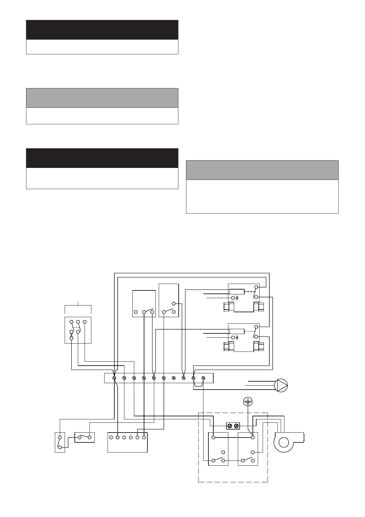
2-Port Zone Valve
Motor
Room
Stat
2 1 3
230V
50HZ
L N E
5A
2-Port Zone Valve
Motor
1 2 3 4 5 6 7 8 9 10
HTG
HW
Wiring
Centre
Grey
Orange
Orange
Brown
Blue
Green/Yellow
Green/Yellow
Brown
Blue
Brown
Blue
Green/Yellow
Cylinder
Stat
1
C
2
Blue
Green/Yellow
Brown
E
N
L
Link
Pump
N
2-Channel
Programmer
L
Frost
Thermostat
Pipe Stat
(If fitted)
OFFOFF ON ON
HW HT HW HT
Overheat
Stat
1
C
2
Control
Stat
1
C
2
Link
Burner
L N E
Earth Stud on
top of Boiler
Green/Yellow
Blue
Brown
Blue
Green/Yellow
Refer to Figure 8-3 for connection details
Figure 8-1: 2 x 2-port valve control system
8.4 WIRING DIAGRAMS
! WARNING !
DO NOT connect the neutral wires to either of the two
thermostats.
6. There are NO connections to terminal 1 on the overheat
thermostat and terminal 2 on the control thermostat.
7. Position the support bushes so as not to strain the
connections when the cover is replaced. Place the cover in
position locating the bushes at the same time.
! NOTE !
It may be necessary to rotate the thermostat knob to
engage it on the operating spindle as the cover is replaced.
8. Secure the cover in position by tightening the three screws.
Tighten the cable support bush nuts to secure the cables.
9. Ensure that all external wiring is adequately supported.
! WARNING !
After completing electrical connections and before
reconnecting the electrical supply to the boiler, ensure the
dual thermostat cover is properly secured.
10. Re-connect the electrical supply and check operation of
heating system controls (programmer, room thermostats,
etc.).
11. Refer to Instructions provided with the programmer for
operation and setting.
12. Leave the Programmer and Thermostat Instructions with the
user after installation for their future reference.
BURNER LEAD PLUG/SOCKET CONNECTOR
On all models, the electrical cable between the boiler control
panel and burner is now tted with an in-line 3-way plug
and socket connector. This enables the burner to be easily
disconnected from the boiler control panel for ease of removal
and servicing.
8.3 FROST PROTECTION
For additional protection of either the entire heating system, or
the boiler and localised pipework, it is recommended that a frost
thermostat be installed.
Refer to Figures 8-1 & 8-2 (as appropriate) for connection details.
To protect the heating system, the frost thermostat should be sited
within the house in such a place that it can detect any rise and fall
in the ambient air temperature, i.e. in a room with a radiator.
Where the frost thermostat is installed outside the house (to
protect a boiler installed in an external boiler room or garage) or
in an attic, it is recommended that it be used in conjunction with a
pipe thermostat to avoid unnecessary and wasteful overheating of
the property.
The pipe thermostat should be located on the boiler return pipe,
and set to operate at 25°C.
! NOTE !
For total system protection against freezing, particularly
during extended periods without electrical power, Grant
recommend the use of a combined heating system
antifreeze and corrosion inhibitor, used in accordance with
the manufacturer’s instructions.