5.1 GENERAL
The ow and return pipework can be routed to either side of the
boiler, dependant on the type and direction of the ue system
used.
For condensate disposal pipework refer to Section 6.
A drain cock is supplied in the accessories pack and should be
tted at the bottom on the front of the boiler to allow the boiler to
be drained.
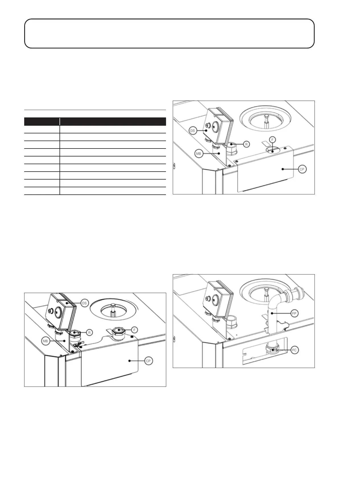
Key to diagrams
Key
F Flow
FP Flow pipe
FC Flow connection
R Return
MB Mounting bracket
DS Dual stat
CP Removable cover plate
P Pockets
SP Split pin
5.2 15-26 MODELS
FLOW CONNECTION
A 1ʺ BSP socket is provided for the boiler ow connection. This is
located on the top of the boiler towards the right hand side. Refer
to Figure 5-1.
The ow pipe from the boiler will need to be vented as it is the
highest point on the primary heat exchanger.
RETURN CONNECTION
A second 1ʺ BSP socket is provided for the boiler return
connection. This is located on the top of the boiler towards the
front on the right hand side. Refer to Figure 5-1.
The return pipe to the boiler will also need to be vented as it is the
highest point on the secondary heat exchanger.
Figure 5-1: 15-26 models - dual stat/mounting bracket, ow and
return connections and removable cover plate
5.3 26-46 MODEL ONLY
FLOW CONNECTION
A 28mm compression connection is supplied for the boiler ow
connection. This is located on the right hand side of the boiler
behind a removable cover plate. To gain access to the connection,
unscrew and remove the two screws from the top ange of the
cover plate and remove cover plate from boiler. Refer to Figure
5-2.
Figure 5-2: 26-46 model - dual stat/mounting bracket, ow and
return connections and removable cover plate
A bent 28mm ow pipe, with two thermostat pockets, is supplied
with the boiler to be tted into the ow connection, as follows:
1. With the cover plate removed, loosen the compression nut
and t the longer leg of the bent ow pipe into the connection.
2. Ensure that the pipe is vertical and fully pushed into the
connection.
3. With the open end of the ow pipe pointing in the required
direction (see below), fully tighten the compression nut. Refer
to Figure 5-3.
4. Replace cover plate and secure with the two screws
previously removed.
Figure 5-3: 26-46 model - ow pipe tted (cover plate removed)
The direction of the bent ow pipe will depend on the ue system
being used with the boiler.
If a Grant low level balanced ue (Yellow System) or external
balanced ue system (Green System) is used, the ow pipe must
be positioned as follows:
• If the ue points towards the right of the boiler (viewed from
the front), the ow pipe must be set to point either to the right
or to the front of the boiler to avoid clashing with the ue.
• If the ue points towards the rear of the boiler, the ow pipe
must be set to point either to the rear, to the right or to the
front of the boiler to avoid clashing with the ue.
• If the ue points towards the left of the boiler (viewed from
the front), the ow pipe must be set to point either to the rear,
to the right or to the front of the boiler to avoid clashing with
the ue.
Section 5: Pipe Connections Page 17
5 PIPE CONNECTIONS